Page 20 of 2248
G2M0093
4) Connect oil pressure gauge hose to cylinder block.
5) Start the engine, and measure oil pressure.
Oil pressure:
98 kPa (1.0 kg/cm
2,14 psi) or more at 800 rpm
294 kPa (3.0 kg/cm2, 43 psi) or more at 5,000 rpm
CAUTION:
�If oil pressure is out of specification, check oil
pump, oil filter and lubrication line.
�If oil pressure warning light is turned ON and oil
pressure is in specification, replace oil pressure
switch.
NOTE:
The specified data is based on an engine oil temperature
of 80°C (176°F).
6) After measuring oil pressure, install oil pressure switch.
Tightening torque:
25±3 N⋅m (2.5±0.3 kg-m, 18.1±2.2 ft-lb)
7) Install generator and V-belt in the reverse order of
removal, and adjust the V-belt deflection.
8
2-2
6. Engine Oil Pressure
Page 73 of 2248
G2M0163
7) Removal of oil pan
(1) Turn cylinder block with #2 and #4 piston sides
facing upward.
(2) Remove bolts which secure oil pan to cylinder
block.
(3) Insert a oil pan cutter blade between cylinder block-
to-oil pan clearance and remove oil pan.
CAUTION:
Do not use a screwdriver or similar tool in place of oil-
pan cutter.
8) Remove oil strainer stay.
9) Remove oil strainer.
10) Remove baffle plate.
11) Remove oil filter.
B: DISASSEMBLY
1. PISTON PIN AND CYLINDER BLOCK
CONNECTING BOLT
G2M0164
52
2-3SERVICE PROCEDURE
7. Cylinder Block
Page 95 of 2248
B2M0390A
(2) Apply fluid packing to matching surface of oil pump.
Fluid packing:
THREE BOND 1215 or equivalent
(3) Install oil pump on cylinder block. Be careful not to
damage oil seal during installation.
CAUTION:
�Do not forget to install O-ring and seal when install-
ing oil pump.
�Align flat surface of oil pump’s inner rotor with
crankshaft before installation.
G2M0628
9) Install engine coolant pump and gasket.
CAUTION:
�Be sure to use a new gasket.
�When installing engine coolant pump, tighten bolts
in two stages in numerical sequence as shown in Fig-
ure.
10) Install engine coolant pipe.
11) Install oil filter.
2. RELATED PARTS
1) Install cylinder head and intake manifold.
2) Install timing belt, camshaft sprocket and related parts.
74
2-3SERVICE PROCEDURE
7. Cylinder Block
Page 98 of 2248
TROUBLE
Engine will not start.
Rough idle and engine stall
Low output, hesitation and poor acceleration
Surging
Engine does not return to idle.
Dieseling (Run-on)
After burning in exhaust system
Knocking
Excessive engine oil consumption
Excessive fuel consumption Starter does not turn.
Initial combustion does not occur.
Initial combustion occurs.
Engine stalls after initial combustion.
LUBRICATION SYSTEM
22 3 3�Incorrect oil pressure
2�Loosened oil pump attaching bolts and defective
gasket
2�Defective oil filter seal
2�Defective crankshaft oil seal
32�Defective rocker cover gasket
2�Loosened oil drain plug or defective gasket
2�Loosened oil pan fitting bolts or defective oil pan
COOLING SYSTEM
33221�Overheating
333�Over cooling
OTHERS
113 3�Malfunction of Evaporative Emission Control
System
21�Stuck or damaged throttle valve
322 2�Accelerator cable out of adjustment
77
2-3DIAGNOSTICS
1. Engine Trouble in General
Page 101 of 2248

1. Lubrication System
A: SPECIFICATIONS
Lubrication methodForced lubrication
Oil pumpPump typeTrochoid type
Number of teethInner rotor 9
Outer rotor 10
Outer rotor diameter x thickness 78x9mm(3.07 x 0.35 in)
Tip clearance between inner and outer rotorSTANDARD 0.04 — 0.14 mm (0.0016 — 0.0055 in)
LIMIT 0.18 mm (0.0071 in)
Side clearance between inner rotor and pump
caseSTANDARD 0.02 — 0.07 mm (0.0008 — 0.0028 in)
LIMIT 0.15 mm (0.0059 in)
Case clearance between outer rotor and pump
caseSTANDARD 0.10 — 0.175 mm (0.0039 — 0.0069 in)
LIMIT 0.20 mm (0.0079 in)
Capacity at
80°C (176°F)700 rpm Discharge- pressure 98 kPa (1.0 kg/cm
2, 14 psi) or more
- quantity 4.2�(4.4 US qt, 3.7 Imp qt)/min.
5,000 rpm Discharge- pressure 294 kPa (3.0 kg/cm
2, 43 psi) or more
- quantity 42.0�(11.10 US gal, 9.24 Imp gal)/min.
Relief valve operation pressure 490 kPa (5.0 kg/cm
2, 71 psi)
Oil filterTypeFull-flow filter type
Filtration area 1,000 cm
2(155 sq in)
By-pass valve opening pressure 157 kPa (1.6 kg/cm
2, 23 psi)
Outer diameter x width 80 x 70 mm (3.15 x 2.76 in)
Oil filter to engine thread size M 20 x 1.5
Relief valve (on rocker shaft) operation pressure 69 kPa (0.7kg/cm
2, 10 psi)
Oil pressure
switchTypeImmersed contact point type
Working voltage — wattage 12 V — 3.4 W or less
Warning light activation pressure 14.7 kPa (0.15 kg/cm
2, 2.1 psi)
Proof pressure More than 981 kPa (10 kg/cm
2, 142 psi)
Oil pan capacity4.0�(4.2 US qt, 3.5 Imp qt)
2
2-4SPECIFICATIONS AND SERVICE DATA
1. Lubrication System
Page 102 of 2248
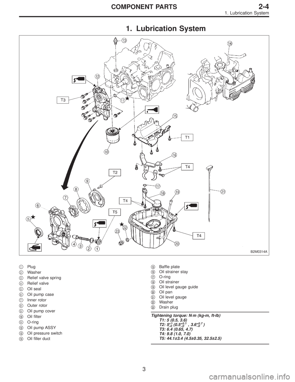
1. Lubrication System
B2M0314A
�1Plug
�
2Washer
�
3Relief valve spring
�
4Relief valve
�
5Oil seal
�
6Oil pump case
�
7Inner rotor
�
8Outer rotor
�
9Oil pump cover
�
10Oil filter
�
11O-ring
�
12Oil pump ASSY
�
13Oil pressure switch
�
14Oil filler duct�
15Baffle plate
�
16Oil strainer stay
�
17O-ring
�
18Oil strainer
�
19Oil level gauge guide
�
20Oil pan
�
21Oil level gauge
�
22Washer
�
23Drain plug
Tightening torque: N⋅m (kg-m, ft-lb)
T1: 5 (0.5, 3.6)
T2: 5
+1
�0(0.5+0.1
�0, 3.6+0.7
�0)
T3: 6.4 (0.65, 4.7)
T4: 9.8 (1.0, 7.0)
T5: 44.1±3.4 (4.5±0.35, 32.5±2.5)
3
2-4COMPONENT PARTS
1. Lubrication System
Page 116 of 2248
 O")
1. Engine Lubrication System
Before troubleshooting, make sure that the engine oil level
is correct and no oil leakage exists.
Trouble Possible cause Corrective action
1. Warning light remains
on.1) Oil pressure switch
failureCracked diaphragm or oil leakage within switch Replace.
Broken spring or seized contacts Replace.
2) Low oil pressureClogged oil filter Replace.
Malfunction of oil by-pass valve of oil filter Clean or replace.
Malfunction of oil relief valve of oil pump Clean or replace.
Clogged oil passage Clean.
Excessive tip clearance and side clearance of oil
pump rotor and gearReplace.
Clogged oil strainer or broken pipe Clean or replace.
3) No oil pressureInsufficient engine oil Replenish.
Broken pipe of oil strainer Replace.
Stuck oil pump rotor Replace.
2. Warning light does not
go on.1) Burn-out bulb Replace.
2) Poor contact of switch contact points Replace.
3) Disconnection of wiring Repair.
3. Warning light flickers
momentarily.1) Poor contact at terminals Repair.
2) Defective wiring harness Repair.
3) Low oil pressureCheck for the same pos-
sible causes as listed in
1.—2)
16
2-4DIAGNOSTICS
1. Engine Lubrication System
Page 364 of 2248
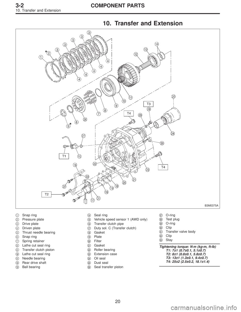
10. Transfer and Extension
B3M0375A
�1Snap ring
�
2Pressure plate
�
3Drive plate
�
4Driven plate
�
5Thrust needle bearing
�
6Snap ring
�
7Spring retainer
�
8Lathe cut seal ring
�
9Transfer clutch piston
�
10Lathe cut seal ring
�
11Needle bearing
�
12Rear drive shaft
�
13Ball bearing�
14Seal ring
�
15Vehicle speed sensor 1 (AWD only)
�
16Transfer clutch pipe
�
17Duty sol. C (Transfer clutch)
�
18Gasket
�
19Plate
�
20Filter
�
21Gasket
�
22Roller bearing
�
23Extension case
�
24Oil seal
�
25Dust seal
�
26Seal transfer piston�
27O-ring
�
28Test plug
�
29O-ring
�
30Clip
�
31Transfer valve body
�
32Clip
�
33Stay
Tightening torque: N⋅m (kg-m, ft-lb)
T1: 7±1 (0.7±0.1, 5.1±0.7)
T2: 8±1 (0.8±0.1, 5.8±0.7)
T3: 13±1 (1.3±0.1, 9.4±0.7)
T4: 25±2 (2.5±0.2, 18.1±1.4)
20
3-2COMPONENT PARTS
10. Transfer and Extension
 Connect oil pressure gauge hose to cylinder block.
5) Start the engine, and measure oil pressure.
Oil pressure:
98 kPa (1.0 kg/cm
2,14 psi) or more at 800 rpm
294 kPa (3.0 kg/cm2, 43 psi) o")
 Removal of oil pan
(1) Turn cylinder block with #2 and #4 piston sides
facing upward.
(2) Remove bolts which secure oil pan to cylinder
block.
(3) Insert a oil pan cutter blade between cyli")
 Apply fluid packing to matching surface of oil pump.
Fluid packing:
THREE BOND 1215 or equivalent
(3) Install oil pump on cylinder block. Be careful not to
damage oil seal during installa")

After burning in exhaust system
Knock")