Page 920 of 2248
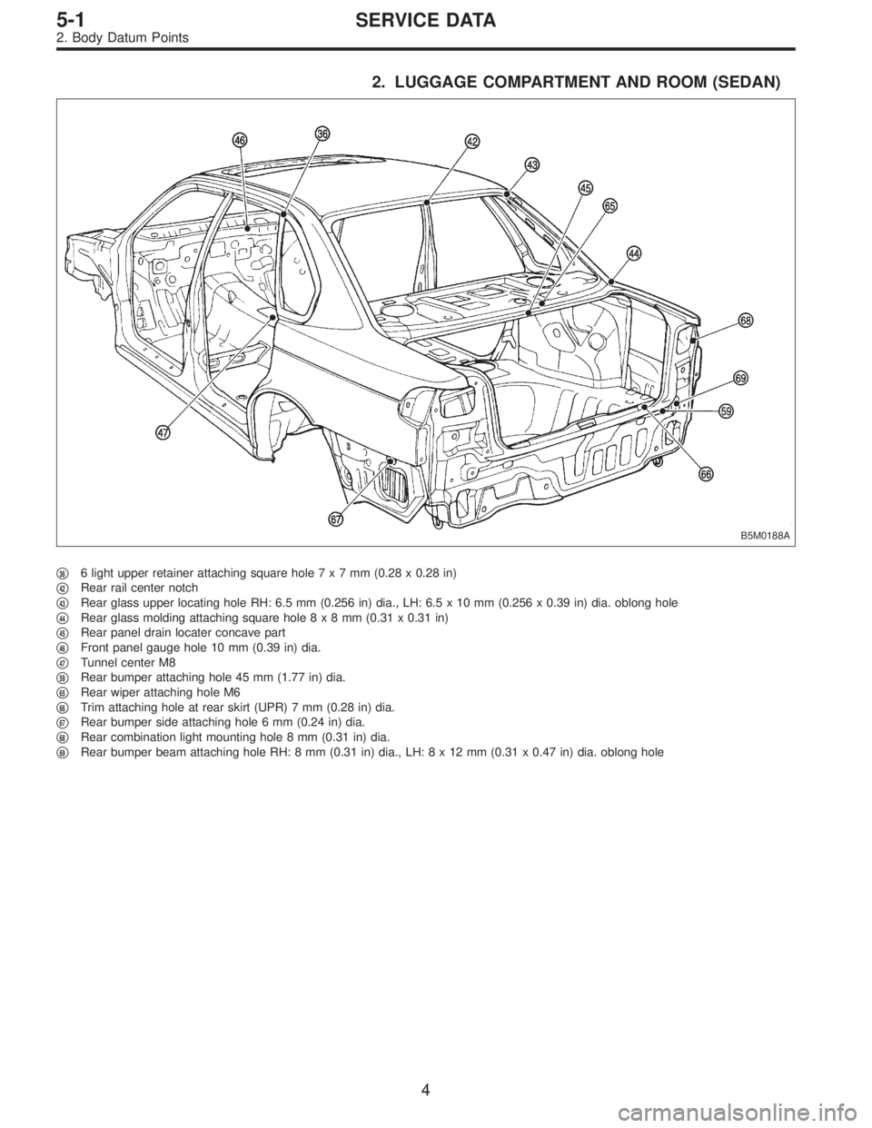
2. LUGGAGE COMPARTMENT AND ROOM (SEDAN)
B5M0188A
�366 light upper retainer attaching square hole7x7mm(0.28 x 0.28 in)
�
42Rear rail center notch
�
43Rear glass upper locating hole RH: 6.5 mm (0.256 in) dia., LH: 6.5 x 10 mm (0.256 x 0.39 in) dia. oblong hole
�
44Rear glass molding attaching square hole8x8mm(0.31 x 0.31 in)
�
45Rear panel drain locater concave part
�
46Front panel gauge hole 10 mm (0.39 in) dia.
�
47Tunnel center M8
�
59Rear bumper attaching hole 45 mm (1.77 in) dia.
�
65Rear wiper attaching hole M6
�
66Trim attaching hole at rear skirt (UPR) 7 mm (0.28 in) dia.
�
67Rear bumper side attaching hole 6 mm (0.24 in) dia.
�
68Rear combination light mounting hole 8 mm (0.31 in) dia.
�
69Rear bumper beam attaching hole RH: 8 mm (0.31 in) dia., LH:8x12mm(0.31 x 0.47 in) dia. oblong hole
4
5-1SERVICE DATA
2. Body Datum Points
Page 921 of 2248
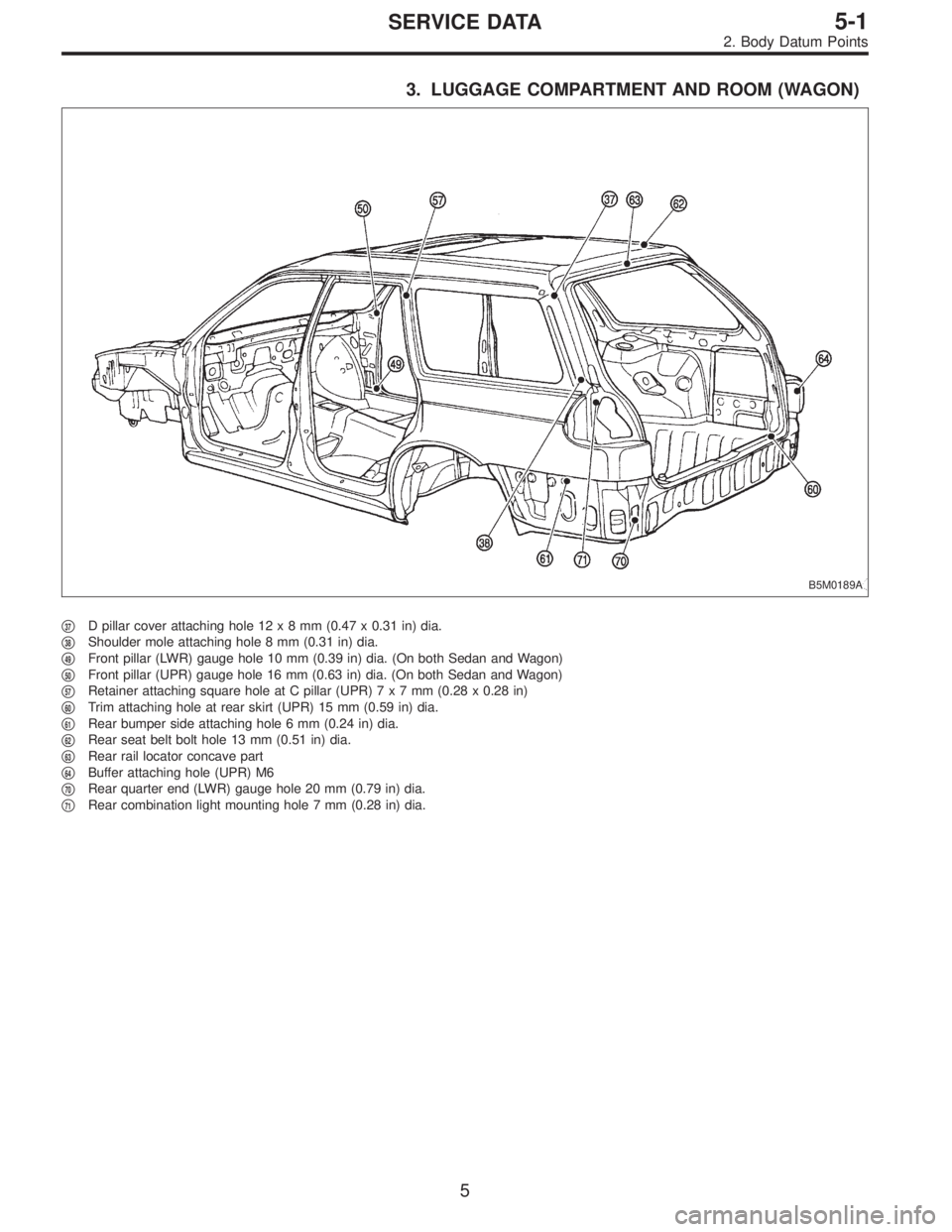
3. LUGGAGE COMPARTMENT AND ROOM (WAGON)
B5M0189A
�37D pillar cover attaching hole 12x8mm(0.47 x 0.31 in) dia.
�
38Shoulder mole attaching hole 8 mm (0.31 in) dia.
�
49Front pillar (LWR) gauge hole 10 mm (0.39 in) dia. (On both Sedan and Wagon)
�
50Front pillar (UPR) gauge hole 16 mm (0.63 in) dia. (On both Sedan and Wagon)
�
57Retainer attaching square hole at C pillar (UPR)7x7mm(0.28 x 0.28 in)
�
60Trim attaching hole at rear skirt (UPR) 15 mm (0.59 in) dia.
�
61Rear bumper side attaching hole 6 mm (0.24 in) dia.
�
62Rear seat belt bolt hole 13 mm (0.51 in) dia.
�
63Rear rail locator concave part
�
64Buffer attaching hole (UPR) M6
�
70Rear quarter end (LWR) gauge hole 20 mm (0.79 in) dia.
�
71Rear combination light mounting hole 7 mm (0.28 in) dia.
5
5-1SERVICE DATA
2. Body Datum Points
Page 1096 of 2248
, 100 minutes (AT)
Cold cranking ampere 430 amperes (MT), 490 amperes (AT)
Fuse10 A, 15 A, 20 A
Combination
meterSpeedometer")
1. Body Electrical
A: SPECIFICATIONS
BatteryReserve capacity 82 minutes (MT), 100 minutes (AT)
Cold cranking ampere 430 amperes (MT), 490 amperes (AT)
Fuse10 A, 15 A, 20 A
Combination
meterSpeedometer Electric pulse type
Tachometer Electric impulse type
Water temperature gauge Thermistor cross coil type
Fuel gauge Resistance cross coil type
Charge indicator light 12 V—1.4 W
Brake fluid level warning/parking brake indicator light 12 V—1.4 W
AT oil temperature warning light (AWD only) 12 V—1.4 W
A.B.S. warning light 12 V—1.4 W
CHECK ENGINE warning light
(Malfunction indicator lamp)12 V—1.4 W
Oil pressure warning light 12 V—1.4 W
AIRBAG system warning light 12 V—1.4 W
Low fuel warning light 12 V—3W
FWD indicator light 12 V—1.4 W
TCS warning light 12 V—1.4 W
TCS indicator light 12 V—1.4 W
Turn signal indicator light 12 V—1.4 W (2 pieces)
Seat belt warning light 12 V—1.4 W
Door open warning light 12 V—1.4 W
Headlight beam indicator light 12 V—1.4 W
Meter illumination light12 V—3 W (2 pieces)
12 V—3.4 W (4 pieces)
Headlight 12 V—60/55 W (Halogen)
Front clearance light 12 V—5W
Turn signal lightFront 12 V—21 W
Rear 12 V—21 W
Tail/Stop light 12 V—5/21 W
Back-up light 12 V—21 W
High-mount stop light12 V—18 W (SEDAN), 12 V—13 W
(WAGON)
License plate light 12 V—5W
Room light 12 V—8W
Trunk room light (SEDAN) 12 V—5W
Luggage room light (WAGON) 12 V—5W
Spot light 12 V—8 W (2 pieces)
Glove box light 12 V—3.4 W
Ash tray illumination light 12 V—1.7 W
Selector lever illumination light (AT model) 12 V—1.7 W
2
6-2SPECIFICATIONS
1. Body Electrical
Page 1117 of 2248
![SUBARU LEGACY 1995 Service Repair Manual 7. Back-up Light
A: REMOVAL AND INSTALLATION
1. BACK-UP LIGHT
Refer to 6-2 [W5A2] as for removal and installation of rear
finisher.
2. BACK-UP LIGHT SWITCH (MT MODEL)
Refer to 3-1 [W2B1 (AWD) or W3A0](/manual-img/17/57432/w960_57432-1116.png "SUBARU LEGACY 1995 Service Repair Manual 7. Back-up Light
A: REMOVAL AND INSTALLATION
1. BACK-UP LIGHT
Refer to 6-2 [W5A2] as for removal and installation of rear
finisher.
2. BACK-UP LIGHT SWITCH (MT MODEL)
Refer to 3-1 [W2B1 (AWD) or W3A0")
7. Back-up Light
A: REMOVAL AND INSTALLATION
1. BACK-UP LIGHT
Refer to 6-2 [W5A2] as for removal and installation of rear
finisher.
2. BACK-UP LIGHT SWITCH (MT MODEL)
Refer to 3-1 [W2B1 (AWD) or W3A0 (FWD)] as for removal
and installation of back-up light switch.
3. INHIBITOR SWITCH (AT MODEL)
Refer to 3-2 [W4A4] as for removal and installation of
inhibitor switch (R position switch).
B: INSPECTION
1. INHIBITOR SWITCH (AT MODEL)
Refer to 3-2 [W2B2] as for inspection of inhibitor switch.
B6M0068
8. Room Light and Door Switch
A: REMOVAL AND INSTALLATION
1. ROOM LIGHT
1) Pry room light lens off using a screwdriver.
2) Remove screws which secure room light body.
3) Remove room light body while disconnecting connector.
B6M0345A
2. TRUNK ROOM LIGHT (SEDAN)
1) Turn trunk room light body by hand and remove it from
rear shelf panel.
2) Disconnect connector of trunk room light.
B6M0069
3. LUGGAGE ROOM LIGHT (WAGON)
1) Pry luggage room light lens off using a screwdriver.
2) Remove screws which secure luggage room light body.
3) Remove luggage room light body while disconnecting
connector.
20
6-2SERVICE PROCEDURE
7. Back-up Light - 8. Room Light and Door Switch
Page 1118 of 2248
![SUBARU LEGACY 1995 Service Repair Manual 7. Back-up Light
A: REMOVAL AND INSTALLATION
1. BACK-UP LIGHT
Refer to 6-2 [W5A2] as for removal and installation of rear
finisher.
2. BACK-UP LIGHT SWITCH (MT MODEL)
Refer to 3-1 [W2B1 (AWD) or W3A0](/manual-img/17/57432/w960_57432-1117.png "SUBARU LEGACY 1995 Service Repair Manual 7. Back-up Light
A: REMOVAL AND INSTALLATION
1. BACK-UP LIGHT
Refer to 6-2 [W5A2] as for removal and installation of rear
finisher.
2. BACK-UP LIGHT SWITCH (MT MODEL)
Refer to 3-1 [W2B1 (AWD) or W3A0")
7. Back-up Light
A: REMOVAL AND INSTALLATION
1. BACK-UP LIGHT
Refer to 6-2 [W5A2] as for removal and installation of rear
finisher.
2. BACK-UP LIGHT SWITCH (MT MODEL)
Refer to 3-1 [W2B1 (AWD) or W3A0 (FWD)] as for removal
and installation of back-up light switch.
3. INHIBITOR SWITCH (AT MODEL)
Refer to 3-2 [W4A4] as for removal and installation of
inhibitor switch (R position switch).
B: INSPECTION
1. INHIBITOR SWITCH (AT MODEL)
Refer to 3-2 [W2B2] as for inspection of inhibitor switch.
B6M0068
8. Room Light and Door Switch
A: REMOVAL AND INSTALLATION
1. ROOM LIGHT
1) Pry room light lens off using a screwdriver.
2) Remove screws which secure room light body.
3) Remove room light body while disconnecting connector.
B6M0345A
2. TRUNK ROOM LIGHT (SEDAN)
1) Turn trunk room light body by hand and remove it from
rear shelf panel.
2) Disconnect connector of trunk room light.
B6M0069
3. LUGGAGE ROOM LIGHT (WAGON)
1) Pry luggage room light lens off using a screwdriver.
2) Remove screws which secure luggage room light body.
3) Remove luggage room light body while disconnecting
connector.
20
6-2SERVICE PROCEDURE
7. Back-up Light - 8. Room Light and Door Switch
Page 1119 of 2248
 Remove rubber boot of door switch.
2) Remove screw which secures door switch to body.
3) Remove door switch while disconnecting connector.
5. TRUNK ROOM LIGHT SWITCH (SEDAN)")
B6M0070A
4. DOOR SWITCH
1) Remove rubber boot of door switch.
2) Remove screw which secures door switch to body.
3) Remove door switch while disconnecting connector.
5. TRUNK ROOM LIGHT SWITCH (SEDAN)
Refer to 5-1 [W2A3] as for removal and installation of trunk
room light switch which is installed in trunk lid lock.
6. LUGGAGE ROOM LIGHT SWITCH (WAGON)
Refer to 5-2 [W3A2] as for removal and installation of lug-
gage room light switch which is installed in rear gate lock.
B6M0071
B: INSPECTION
1. DOOR SWITCH
Move switch and check continuity between terminal of door
switch and switch body.
Switch position Terminal Switch body
Open (ON)��
Push in (OFF)
B6M0072A
2. TRUNK ROOM LIGHT SWITCH (SEDAN)
Move switch and check continuity between terminals of
trunk room light switch.
Terminal
Switch position12
Open (ON)��
Push in (OFF)
B6M0073A
3. LUGGAGE ROOM LIGHT SWITCH (WAGON)
Move switch and check continuity between terminals of
luggage room light switch.
Terminal
Switch position12
Open (ON)��
Push in (OFF)
21
6-2SERVICE PROCEDURE
8. Room Light and Door Switch
Page 1158 of 2248

NOTE:
The rear gate switch is united with the rear gate latch
assembly.
1) Remove rear gate trim panel.
2) Disconnect rod from rear gate latch assembly.
3) Disconn")
B6M0372A
8. REAR GATE SWITCH (WAGON)
NOTE:
The rear gate switch is united with the rear gate latch
assembly.
1) Remove rear gate trim panel.
2) Disconnect rod from rear gate latch assembly.
3) Disconnect rear gate switch (combined with luggage
room light switch) connector and power door lock actuator
connector.
4) Remove bolts which secure power door lock actuator.
5) Remove bolts which secure latch.
6) Remove latch and actuator assembly.
7) Installation is in the reverse order of removal.
B6M0373A
9. SECURITY INDICATOR LIGHT
1) Remove screws which secure meter visor.
2) Remove meter visor from instrument panel while dis-
connecting connectors.
3) Remove security indicator light from meter visor.
4) Installation is in the reverse order of removal.
B6M0682A
10. SECURITY CONTROL MODULE
1) Follow the same preparatory procedures when remov-
ing door lock timer.
2) Remove nut which secures security control module,
and remove security control module from bracket while
pulling right side lower end of instrument panel.
CAUTION:
Be careful not to damage instrument panel while pull-
ing its right side lower end.
3) Disconnect connector from security control module.
4) Installation is in the reverse order of removal.
54
6-2SERVICE PROCEDURE
22. Security System
Page 1162 of 2248
6. DOOR SWITCH
Refer to 6-2 [W8B1] as for inspection of door switch.
NOTE:
The door switch is combined with the door switch for room
light.
7. TRUNK LID SWITCH (SEDAN)
Refer to 6-2 [W8B2] as for inspection of trunk lid switch.
NOTE:
The trunk lid switch is combined with the trunk room light
switch.
8. REAR GATE SWITCH (WAGON)
Refer to 6-2 [W8B3] as for inspection of rear gate switch.
NOTE:
The rear gate switch is combined with the luggage room
light switch.
B6M0382A
9. SECURITY INDICATOR LIGHT
1) Remove security indicator light.
2) Check continuity between terminals of security indicator
light.
3) If there is no continuity, the indicator light will be fail-
ured.
Terminals: No. 2—No. 4
10. SECURITY CONTROL MODULE
Refer to 6-2 [K600]:“6. SECURITY SYSTEM”for inspec-
tion of security control module.
58
6-2SERVICE PROCEDURE
22. Security System
![SUBARU LEGACY 1995 Service Repair Manual 6. DOOR SWITCH
Refer to 6-2 [W8B1] as for inspection of door switch.
NOTE:
The door switch is combined with the door switch for room
light.
7. TRUNK LID SWITCH (SEDAN)
Refer to 6-2 [W8B2] as for inspe](/manual-img/17/57432/w960_57432-1161.png "SUBARU LEGACY 1995 Service Repair Manual 6. DOOR SWITCH
Refer to 6-2 [W8B1] as for inspection of door switch.
NOTE:
The door switch is combined with the door switch for room
light.
7. TRUNK LID SWITCH (SEDAN)
Refer to 6-2 [W8B2] as for inspe")