Page 233 of 2248
")
1. Clutch System
Condition Possible cause and testing Corrective action
1. Clutch slip-
pageIt is hard to perceive clutch slippage in the early stage, but pay attention to the following symptoms.
(a) Engine revs up when shifting.
(b) High speed driving is impossible; especially rapid acceleration impossible and vehicle speed does not increase in
proportion to an increase in engine speed.
(c) Power falls, particularly when ascending a slope, and there is a smell of burning of the clutch facing.
�Method of testing: Put the vehicle in stationary condition with parking brake fully applied. Disengage the clutch and
shift the transmission gear into the first. Gradually allow the clutch to engage while gradually increasing the engine
speed. The clutch function is satisfactory if the engine stalls. However, the clutch is slipping if the vehicle does not
start off and the engine does not stall.
(a) No clutch pedal play Readjust.
(b) No release lever end play Readjust.
(c) Clutch facing smeared by oil Replace.
(d) Worn clutch facing Replace.
(e) Deteriorated diaphragm spring Replace.
(f ) Distorted pressure plate or flywheel Correct or replace.
(g) Defective release bearing holder Correct or replace.
(h) Defective pedal and cable system Correct or replace.
2. Clutch
drags.As a symptom of this trouble, a harsh scratching noise develops and control becomes quite difficult when shifting
gears. The symptom becomes more apparent when shifting into the first gear. However, because much trouble of the
this sort is due to defective synchronization mechanism, carry out the test as described after.
�Method of testing: Refer to DIAGNOSTIC DIAGRAM on page after.
It may be judged as insufficient disengagement of clutch if any noise occurs during this test.
(a) Excessive clutch pedal play Readjust.
(b) Excessive clutch release lever play Readjust.
(c) Worn or rusty clutch disc hub spline Replace clutch disc.
(d) Excessive deflection of clutch disc facing Correct or replace.
(e) Seized crankshaft pilot needle bearing Replace.
(f ) Malfunction of pedal and cable system Correct or replace.
(g) Cracked clutch disc facing Replace.
(h) Sticked clutch disc (smeared by oil or water) Replace.
3. Clutch chat-
ters.Clutch chattering is an unpleasant vibration to the whole body when the vehicle is just started with clutch partially
engaged.
(a) Improper clutch cable routing Correct.
(b) Adhesion of oil on the facing Replace clutch disc.
(c) Weak or broken torsion spring Replace clutch disc.
(d) Defective facing contact or excessive disc Replace clutch disc defection.
(e) Warped pressure plate or flywheel Correct or replace.
(f ) Loose disc rivets Replace clutch disc.
(g) Loose engine mounting Retighten or replace mounting.
(h) Improper adjustment of pitching stopper Adjustment.
11
2-10DIAGNOSTICS
1. Clutch System
Page 235 of 2248
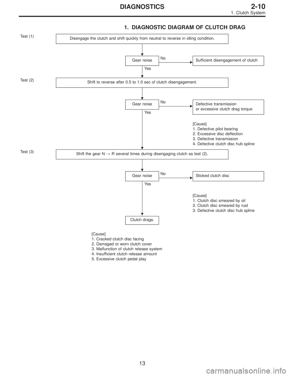
1. DIAGNOSTIC DIAGRAM OF CLUTCH DRAG
Test (1)
Disengage the clutch and shift quickly from neutral to reverse in idling condition.
Gear noise
Ye s
�No
Sufficient disengagement of clutch
Test (2)
Shift to reverse after 0.5 to 1.0 sec of clutch disengagement.
Gear noise
Ye s
�No
Defective transmission
or excessive clutch drag torque
[Cause]
1. Defective pilot bearing
2. Excessive disc deflection
3. Defective transmission
4. Defective clutch disc hub spline
Test (3)
Shift the gear N,R several times during disengaging clutch as test (2).
Gear noise
Ye s
�No
Sticked clutch disc
[Cause]
1. Clutch disc smeared by oil
2. Clutch disc smeared by rust
3. Defective clutch disc hub spline
Clutch drags.
[Cause]
1. Cracked clutch disc facing
2. Damaged or worn clutch cover
3. Malfunction of clutch release system
4. Insufficient clutch release amount
5. Excessive clutch pedal play
�
�
�
�
�
�
13
2-10DIAGNOSTICS
1. Clutch System
Page 784 of 2248
�Be careful to prevent foreign particles from getting into
hydraulic unit.
�When a new hydraulic unit is installed, apply a coat of
rust-preventive wax (Nippeco LT or GB) to bracket attach-
ing bolts after tightening.
�Do not pull harness disconnecting harness connector.
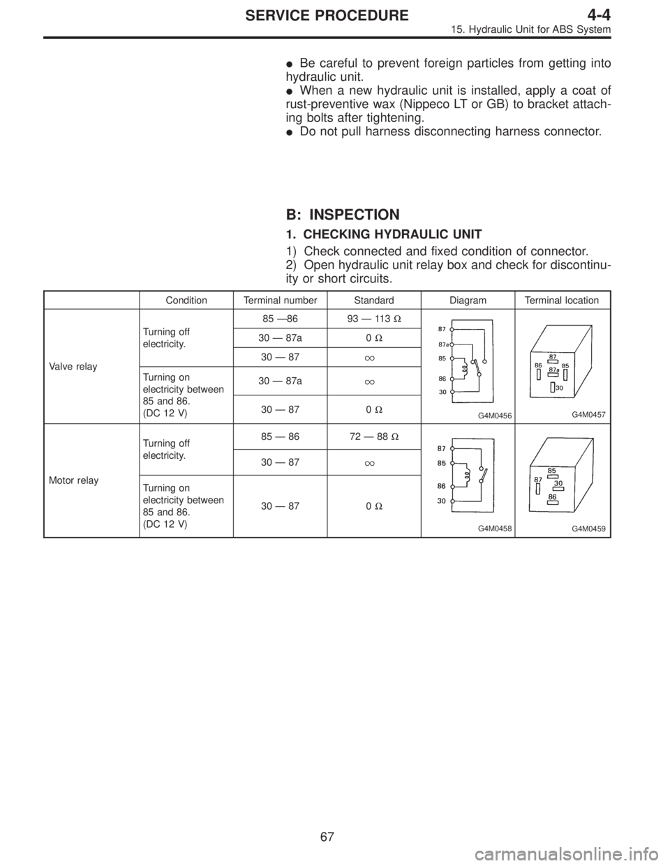
B: INSPECTION
1. CHECKING HYDRAULIC UNIT
1) Check connected and fixed condition of connector.
2) Open hydraulic unit relay box and check for discontinu-
ity or short circuits.
Condition Terminal number Standard Diagram Terminal location
Valve relayTurning off
electricity.85—86 93—11 3Ω
G4M0456G4M0457
30—87a 0Ω
30—87
Turning on
electricity between
85 and 86.
(DC 12 V)30—87a
30—87 0Ω
Motor relayTurning off
electricity.85—86 72—88Ω
G4M0458G4M0459
30—87
Turning on
electricity between
85 and 86.
(DC 12 V)30—87 0Ω
67
4-4SERVICE PROCEDURE
15. Hydraulic Unit for ABS System
Page 805 of 2248
 Remove bolts which secure hydraulic unit bracket, and
remove hydraulic unit from engine compartment.
CAUTION:
�Hydraulic unit cannot be disassembled. Do not
attempt to loosen bolts and nuts")
B4M0628
5) Remove bolts which secure hydraulic unit bracket, and
remove hydraulic unit from engine compartment.
CAUTION:
�Hydraulic unit cannot be disassembled. Do not
attempt to loosen bolts and nuts.
�Do not drop or bump hydraulic unit.
�Do not turn the hydraulic unit upside down or place
it on its side.
�Be careful to prevent foreign particles from getting
into hydraulic unit.
�Do not pull harness disconnecting harness connec-
tor.
B: INSPECTION
1) Check connected and fixed condition of connector.
2) Check for discontinuity or short circuits.
Condition Terminal number Standard Diagram Terminal location
Valve relayTurning off
electricity.A—B90Ω
B4M0629A
B4M0630
C—F0Ω
C—E
Turning on
electricity between
A and B.
(DC 12 V)C—F
C—E0Ω
Motor relayTurning off
electricity.a—b* 57Ω
B4M0631AB4M0632
c—d
Turning on
electricity between
a and b.
(DC 12 V)c—d0Ω
*: Attach circuit tester positive probe to terminal“a”and its negative probe to terminal“b”and measure the circuit resistance.
86
4-4SERVICE PROCEDURE
20. Hydraulic Unit for ABS/TCS System
Page 1086 of 2248
B6M0489A
1) Diodes on“+”side
Continuity of proper diodes on“+”side
BAT side
(+) (�)
Terminal
N, U, V and W
(+)—Continuity must
not exist.
(�)Continuity
must exist.—
B6M0490A
2) Diodes on“�”side
Continuity of proper diodes on“�”side
“E”side
(+) (�)
Terminal
N, U, V and W
(+)—Continuity must
exist.
(�)Continuity
must not exist.—
CAUTION:
Never use a high tension insulation tester, such as a
meggar as it will damage diodes with its high tension.
B6M0491A
5. IC REGULATOR
1) Compose a circuit diagram as shown in figure.
�
1Voltage meter: 0 to 30 V
�
2Switch 1
�
3Variable DC power supply: Variable 0 to 20 V, 1 A or
more
�
4Lamp 2
�
5Lamp 1
�
6Switch 3
�
7Switch 2
�
8Plus generator: Power supply 5 to 30 V, 1 kHz
20
6-1SERVICE PROCEDURE
2. Generator
Page 1155 of 2248

B6M0361A
22. Security System
A: REMOVAL AND INSTALLATION
1. STARTER INTERRUPT RELAY
NOTE:
The starter interrupt relay and headlight alarm relay use the
same parts and are mounted parallel to each other.
Therefore, before removal and installation, identify the
starter interrupt relay by the color of its wiring connection.
1) Remove instrument panel lower cover.
2) Disconnect connector of starter interrupt relay.
3) Remove starter interrupt relay.
4) Installation is in the reverse order of removal.
B6M0361A
2. HEADLIGHT ALARM RELAY
NOTE:
The headlight alarm relay and starter interrupt relay use the
same parts and are mounted parallel to each other.
Therefore, before removal and installation, identify the
headlight alarm relay by the color of its wiring connection.
1) Remove instrument panel lower cover.
2) Disconnect connector of headlight alarm relay.
3) Remove headlight alarm relay.
4) Installation is in the reverse order of removal.
B6M0363A
3. ENGINE HOOD SWITCH
1) Disconnect connector of engine hood switch from bot-
tom side of switch body.
2) Remove headlight (LH).
3) Remove attaching bolt, and then remove engine hood
switch.
4) Installation is in the reverse order of removal.
51
6-2SERVICE PROCEDURE
22. Security System
Page 1168 of 2248
2. AT Shift Lock System
A: WIRING DIAGRAM
B6M0466
64
6-2DIAGNOSTICS
2. AT Shift Lock System
Page 1279 of 2248
6. Wiring Diagram and Wiring Harness
A: WIRING DIAGRAM
1. ENGINE ELECTRICAL SYSTEM
�LHD model
BU10-02A
73
2-7ON-BOARD DIAGNOSTICS II SYSTEM
6. Wiring Diagram and Wiring Harness
 Diodes on“+”side
Continuity of proper diodes on“+”side
BAT side
(+) (�)
Terminal
N, U, V and W
(+)—Continuity must
not exist.
(�)Continuity
must exist.—
B6M0490A
2) Diodes on�")