Page 370 of 2248

The point listed above should be checked for fluid leak.
Checking method is as follows:
(1) Place the vehicle in the pit, and check w")
G3M0859
Transmission cover
�Transmission cover (Defective casting)
The point listed above should be checked for fluid leak.
Checking method is as follows:
(1) Place the vehicle in the pit, and check whether the
leaking oil is ATF or not. The ATF is wine red in color,
and can be discriminated easily from engine oil and
gear oil.
(2) Wipe clean the leaking oil and dust from a suspect-
able area, using a non-inflammable organic solvent
such as carbon tetrachloride.
(3) Run the engine to raise the fluid temperature, and
set the selector lever to“D”in order to increase the fluid
pressure and quickly detect a leaking point. Also check
for fluid leaks while shifting select lever to“R”,“2”, and
“1”.
G3M0289
B: ADJUSTMENT
1. BRAKE BAND
If the following abnormal shifting conditions are noted in a
road test, the brake band must be adjusted.
Improper brake band clearances and their symptoms
Clearance Problem
1. Too wide Upshift from 1st directly to 3rd gear occurs.
2. Wide�Engine rpm increases abruptly while upshifting from 1st
to 2nd gear or 3rd to 4th gear.
�Time lag of at least one second occurs during kickdown
operation from 3rd to 2nd gear.
3. Small“Braking”symptom occurs while upshifting from 2nd to 3rd
gear.
4. Too smallUpshifts from 2nd to 4th gear and downshifts from 4th to
2nd gear occur repeatedly.
26
3-2SERVICE PROCEDURE
2. On-Car Service
Page 384 of 2248

B: TIME LAG TEST
1. GENERAL
If the shift lever is shifted while the engine is idling, there
will be a certain time elapse or lag before the shock can be
felt. This is used for checking the condition of the forward
clutch, reverse clutch, low & reverse brake, forward one-
way clutch and low one-way clutch.
CAUTION:
�Perform the test at normal operation fluid tempera-
ture 60 to 80°C (140 to 176°F).
�Be sure to allow a one minute interval between tests.
�Make three measurements and take the average
value.
2. TEST METHODS
1) Fully apply the parking brake.
2) Start the engine.
Check idling speed (A/C OFF).
“N”range: 800±100 rpm
3) Shift the shift lever from“N”to“D”range.
Using a stop watch, measure the time it takes from shift-
ing the lever until the shock is felt.
Time lag: Less than 1.2 seconds
4) In same manner, measure the time lag for“N”,“R”.
Time lag: Less than 1.5 seconds
3. EVALUATION
1) If“N”,“D”time lag is longer than specified:
�Line pressure too low
�Forward clutch worn
�Low one-way clutch not operating properly
2) If“N”,“R”time lag is longer than specified:
�Line pressure too low
�Reverse clutch worn
�Low & reverse brake worn
�Forward one-way clutch not operating properly
40
3-2SERVICE PROCEDURE
3. Performance Test
Page 513 of 2248
 Install rear cover and tighten bolts to specified torque.
Tightening torque:
29±5 N⋅m (3.0±0.5 kg-m, 21.7±3.6 ft-lb)
F: INSTALLATION
To install, reverse the removal sequence.
1) Insta")
G3M1050
19) Install rear cover and tighten bolts to specified torque.
Tightening torque:
29±5 N⋅m (3.0±0.5 kg-m, 21.7±3.6 ft-lb)
F: INSTALLATION
To install, reverse the removal sequence.
1) Install the air breather cap tapping with a plastic ham-
mer.
CAUTION:
Be sure to install new air breather cap.
2) Position front member on body by passing it under park-
ing brake cable and securing to rear differential.
NOTE:
When installing rear differential front member, do not con-
fuse the installation sequence of the upper and lower stop-
pers.
G3M1026
3) Install DOJ of rear drive shaft into rear differential.
to 3-4 [W2A2].>
ST 28099PA090 SIDE OIL SEAL PROTECTOR
G3M1051
4) Installing procedure hereafter is in the reverse order of
removal.
5) After installation, fill differential carrier with gear oil to
the upper plug level.
CAUTION:
Apply fluid packing to plug.
Fluid packing:
THREE BOND 1205 or equivalent
Oil capacity:
0.8�(0.8 US qt, 0.7 Imp qt)
Tightening torque:
44±4 N⋅m (4.5±0.4 kg-m, 32.5±2.9 ft-lb)
37
3-4SERVICE PROCEDURE
2. Rear Differential
Page 537 of 2248
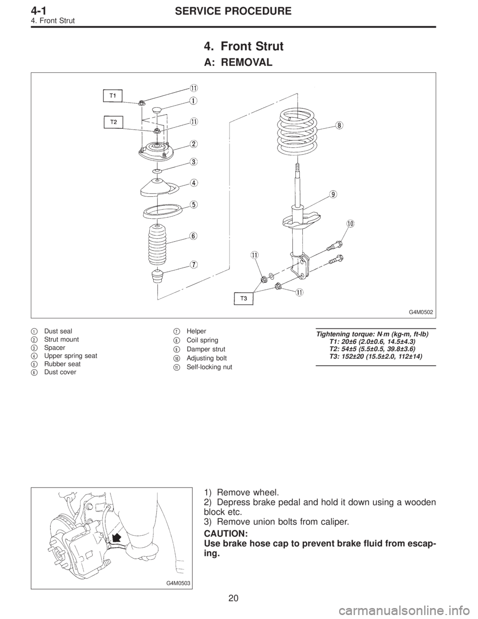
4. Front Strut
A: REMOVAL
G4M0502
�1Dust seal
�
2Strut mount
�
3Spacer
�
4Upper spring seat
�
5Rubber seat
�
6Dust cover�
7Helper
�
8Coil spring
�
9Damper strut
�
10Adjusting bolt
�
11Self-locking nut
Tightening torque: N⋅m (kg-m, ft-lb)
T1: 20±6 (2.0±0.6, 14.5±4.3)
T2: 54±5 (5.5±0.5, 39.8±3.6)
T3: 152±20 (15.5±2.0, 112±14)
G4M0503
1) Remove wheel.
2) Depress brake pedal and hold it down using a wooden
block etc.
3) Remove union bolts from caliper.
CAUTION:
Use brake hose cap to prevent brake fluid from escap-
ing.
20
4-1SERVICE PROCEDURE
4. Front Strut
Page 713 of 2248

While engine is running with/
without steering turned.Loosened installation of oil pump,
oil pump bracketRetighten.
*8
Abnormal inside of oil pump, hoseRepl")
Whine or growl (continuous or
intermittent)
While engine is running with/
without steering turned.Loosened installation of oil pump,
oil pump bracketRetighten.
*8
Abnormal inside of oil pump, hoseReplace oil pump, hose, if the
noise can be heard when running
as well as stand still.
Torque converter growl
air conditioner compression growlRemove power steering pulley
belt and confirm.
Creaking noise (intermittent)
While engine is running with
steering turned.Abnormal inside of gearboxReplace bad parts of gearbox.
Abnormal bearing for steering
shaftApply grease or replace.
*9
Generates when turning steering
wheel with brake (service or park-
ing) applied.If the noise goes off when brake
is released, it is normal.
*10
Vibration
While engine is running with/
without steering turned.
Too low engine speed at startAdjust and instruct customers.
Vane pump aerationFix wrong part.
Vent air.
Damaged valve in oil pump, gear-
boxReplace oil pump, bad parts of
gearbox.
Looseness of play of steering,
suspension partsRetighten.
*8 Oil pump makes whine or growl noise slightly due to its mechanism. Even if the noise can be heard when steering wheel
is turned at stand still there is no abnormal function in the system provided that the noise eliminates when the vehicle is
running.
*9 When stopping with service brake and/or parking brake applied, power steering can be operated easily due to its light
steering effort. If doing so, the disk rotates slightly and makes creaking noise. The noise is generated by creaking between
the disk and pads. If the noise goes off when the brake is released, there is no abnormal function in the system.
*10 There may be a little vibration around the steering devices when turning steering wheel at standstill, even though the com-
ponent parts are properly adjusted and have no defects.
Hydraulic systems are likely to generate this kind of vibration as well as working noise and fluid noise because of com-
bined conditions, i.e., road surface and tire surface, engine speed and turning speed of steering wheel, fluid temperature
and braking condition.
This phenomena does not indicate there is some abnormal function in the system.
The vibration can be known when steering wheel is turned repeatedly at various speeds from slow to rapid step by step
with parking brake applied on concrete road and in“D”range for automatic transmission vehicle.
97
4-3DIAGNOSTICS
1. Power Steering
Page 716 of 2248

9. BREAKAGE OF HOSES
Pressure hose burstExcessive holding time of relief
statusInstruct customers.
Malfunction of relief valveReplace oil pump.
Poor cold characteristic of fluidReplace fluid.
Forced out return hosePoor connectionCorrect.
Poor holding of clipRetighten.
Poor cold characteristic of fluidReplace fluid.
Fluid bleeding out of hose slightlyWrong layout, tensionedReplace hose.
Excessive play of engine due to
deterioration of engine mounting
rubberReplace defective parts.
Improper stop position of pitching
stopperReplace defective parts.
*11
Crack on hose
Excessive holding time of relief
statusReplace.
Instruct customer.
Excessive tightening torque for
return hose clipReplace.
Power steering fluid, brake fluid,
engine oil, electrolyte adhere on
the hose surfaceReplace.
Pay attention on service work.
Too many times use in extremely
cold weatherReplace.
Instruct customers.
*11 Although surface layer materials of rubber hoses have excellent weathering resistance, heat resistance and resistance for
low temperature brittleness, they are likely to be damaged chemically by brake fluid, battery electrolyte, engine oil and
automatic transmission fluid and their service lives are to be very shortened. It is very important to keep the hoses free
from before mentioned fluids and to wipe out immediately when the hoses are adhered with the fluids.
Since resistances for heat or low temperature brittleness are gradually declining according to time accumulation of hot or
cold conditions for the hoses and their service lives are shortening accordingly, it is necessary to perform careful inspec-
tion frequently when the vehicle is used in hot weather areas, cold weather area and/or a driving condition in which many
steering operations are required in short time. Particularly continuous work of relief valve over 5 seconds causes to reduce
service lives of the hoses, the oil pump, the fluid, etc. due to over heat.
So, avoid to keep this kind of condition when servicing as well as driving.
100
4-3DIAGNOSTICS
1. Power Steering
Page 718 of 2248
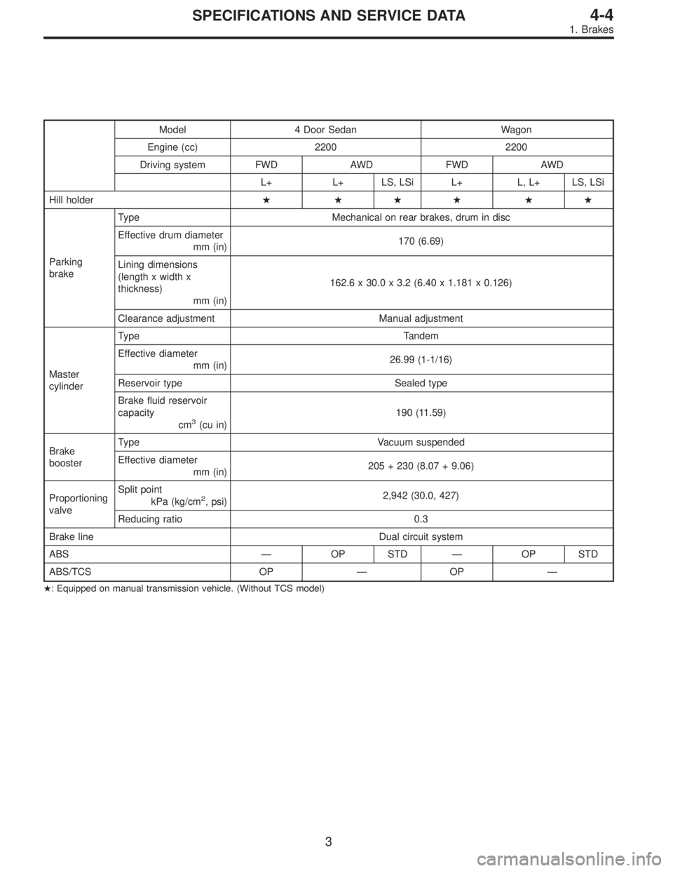
Model 4 Door Sedan Wagon
Engine (cc) 2200 2200
Driving system FWD AWD FWD AWD
L+ L+ LS, LSi L+ L, L+ LS, LSi
Hill holder� ��� ��
Parking
brakeType Mechanical on rear brakes, drum in disc
Effective drum diameter
mm (in)170 (6.69)
Lining dimensions
(length x width x
thickness)
mm (in)162.6 x 30.0 x 3.2 (6.40 x 1.181 x 0.126)
Clearance adjustment Manual adjustment
Master
cylinderType Tandem
Effective diameter
mm (in)26.99 (1-1/16)
Reservoir type Sealed type
Brake fluid reservoir
capacity
cm
3(cu in)190 (11.59)
Brake
boosterType Vacuum suspended
Effective diameter
mm (in)205 + 230 (8.07 + 9.06)
Proportioning
valveSplit point
kPa (kg/cm
2, psi)2,942 (30.0, 427)
Reducing ratio 0.3
Brake line Dual circuit system
ABS—OP STD—OP STD
ABS/TCS OP—OP—
�: Equipped on manual transmission vehicle. (Without TCS model)
3
4-4SPECIFICATIONS AND SERVICE DATA
1. Brakes
Page 720 of 2248
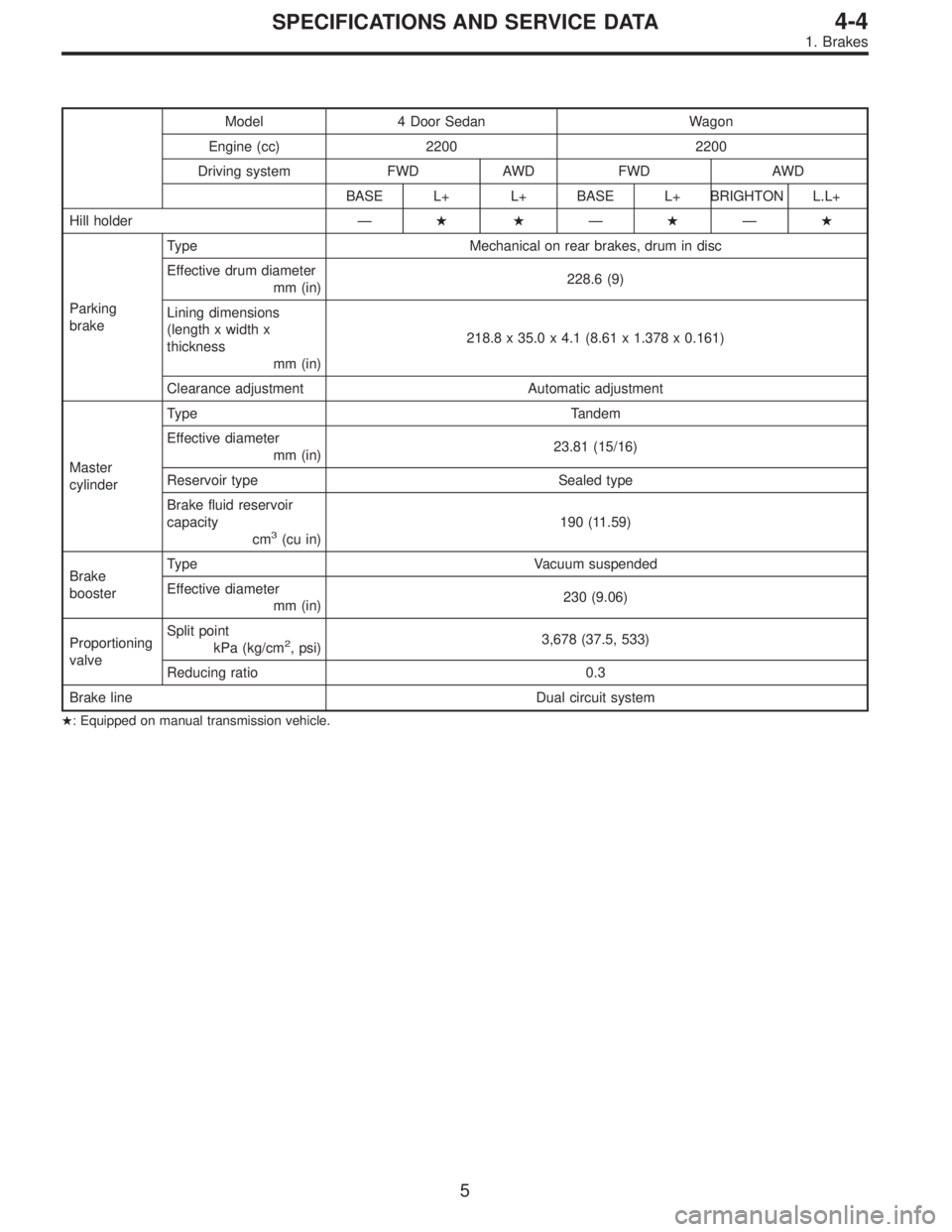
Model 4 Door Sedan Wagon
Engine (cc) 2200 2200
Driving system FWD AWD FWD AWD
BASE L+ L+ BASE L+ BRIGHTON L.L+
Hill holder—��—�—�
Parking
brakeType Mechanical on rear brakes, drum in disc
Effective drum diameter
mm (in)228.6 (9)
Lining dimensions
(length x width x
thickness
mm (in)218.8 x 35.0 x 4.1 (8.61 x 1.378 x 0.161)
Clearance adjustment Automatic adjustment
Master
cylinderType Tandem
Effective diameter
mm (in)23.81 (15/16)
Reservoir type Sealed type
Brake fluid reservoir
capacity
cm
3(cu in)190 (11.59)
Brake
boosterType Vacuum suspended
Effective diameter
mm (in)230 (9.06)
Proportioning
valveSplit point
kPa (kg/cm
2, psi)3,678 (37.5, 533)
Reducing ratio 0.3
Brake line Dual circuit system
�: Equipped on manual transmission vehicle.
5
4-4SPECIFICATIONS AND SERVICE DATA
1. Brakes