Page 20 of 2248
G2M0093
4) Connect oil pressure gauge hose to cylinder block.
5) Start the engine, and measure oil pressure.
Oil pressure:
98 kPa (1.0 kg/cm
2,14 psi) or more at 800 rpm
294 kPa (3.0 kg/cm2, 43 psi) or more at 5,000 rpm
CAUTION:
�If oil pressure is out of specification, check oil
pump, oil filter and lubrication line.
�If oil pressure warning light is turned ON and oil
pressure is in specification, replace oil pressure
switch.
NOTE:
The specified data is based on an engine oil temperature
of 80°C (176°F).
6) After measuring oil pressure, install oil pressure switch.
Tightening torque:
25±3 N⋅m (2.5±0.3 kg-m, 18.1±2.2 ft-lb)
7) Install generator and V-belt in the reverse order of
removal, and adjust the V-belt deflection.
8
2-2
6. Engine Oil Pressure
Page 101 of 2248

1. Lubrication System
A: SPECIFICATIONS
Lubrication methodForced lubrication
Oil pumpPump typeTrochoid type
Number of teethInner rotor 9
Outer rotor 10
Outer rotor diameter x thickness 78x9mm(3.07 x 0.35 in)
Tip clearance between inner and outer rotorSTANDARD 0.04 — 0.14 mm (0.0016 — 0.0055 in)
LIMIT 0.18 mm (0.0071 in)
Side clearance between inner rotor and pump
caseSTANDARD 0.02 — 0.07 mm (0.0008 — 0.0028 in)
LIMIT 0.15 mm (0.0059 in)
Case clearance between outer rotor and pump
caseSTANDARD 0.10 — 0.175 mm (0.0039 — 0.0069 in)
LIMIT 0.20 mm (0.0079 in)
Capacity at
80°C (176°F)700 rpm Discharge- pressure 98 kPa (1.0 kg/cm
2, 14 psi) or more
- quantity 4.2�(4.4 US qt, 3.7 Imp qt)/min.
5,000 rpm Discharge- pressure 294 kPa (3.0 kg/cm
2, 43 psi) or more
- quantity 42.0�(11.10 US gal, 9.24 Imp gal)/min.
Relief valve operation pressure 490 kPa (5.0 kg/cm
2, 71 psi)
Oil filterTypeFull-flow filter type
Filtration area 1,000 cm
2(155 sq in)
By-pass valve opening pressure 157 kPa (1.6 kg/cm
2, 23 psi)
Outer diameter x width 80 x 70 mm (3.15 x 2.76 in)
Oil filter to engine thread size M 20 x 1.5
Relief valve (on rocker shaft) operation pressure 69 kPa (0.7kg/cm
2, 10 psi)
Oil pressure
switchTypeImmersed contact point type
Working voltage — wattage 12 V — 3.4 W or less
Warning light activation pressure 14.7 kPa (0.15 kg/cm
2, 2.1 psi)
Proof pressure More than 981 kPa (10 kg/cm
2, 142 psi)
Oil pan capacity4.0�(4.2 US qt, 3.5 Imp qt)
2
2-4SPECIFICATIONS AND SERVICE DATA
1. Lubrication System
Page 116 of 2248
 O")
1. Engine Lubrication System
Before troubleshooting, make sure that the engine oil level
is correct and no oil leakage exists.
Trouble Possible cause Corrective action
1. Warning light remains
on.1) Oil pressure switch
failureCracked diaphragm or oil leakage within switch Replace.
Broken spring or seized contacts Replace.
2) Low oil pressureClogged oil filter Replace.
Malfunction of oil by-pass valve of oil filter Clean or replace.
Malfunction of oil relief valve of oil pump Clean or replace.
Clogged oil passage Clean.
Excessive tip clearance and side clearance of oil
pump rotor and gearReplace.
Clogged oil strainer or broken pipe Clean or replace.
3) No oil pressureInsufficient engine oil Replenish.
Broken pipe of oil strainer Replace.
Stuck oil pump rotor Replace.
2. Warning light does not
go on.1) Burn-out bulb Replace.
2) Poor contact of switch contact points Replace.
3) Disconnection of wiring Repair.
3. Warning light flickers
momentarily.1) Poor contact at terminals Repair.
2) Defective wiring harness Repair.
3) Low oil pressureCheck for the same pos-
sible causes as listed in
1.—2)
16
2-4DIAGNOSTICS
1. Engine Lubrication System
Page 162 of 2248
B2M0346
17) Disconnect connector from knock sensor.
G2M0416
18) Disconnect connector from camshaft position sensor.
G2M0408
19) Disconnect connector from crankshaft position sensor.
G2M0091
20) Disconnect connector from oil pressure switch.
G2M0296
21) Disconnect fuel hoses from pipes.
WARNING:
Catch fuel from hoses in a container.
11
2-7SERVICE PROCEDURE
4. Intake Manifold
Page 190 of 2248
1. Precautions
WARNING:
�Place “No fire” signs near the working area.
�Disconnect ground terminal from battery.
�Be careful not to spill fuel on the floor.
G2M0340
A: RELEASING OF FUEL PRESSURE
1) Take off floor mat.
2) Remove access hole lid.
B2M0047
3) Disconnect connector from fuel pump.
4) Start the engine, and run it until it stalls.
5) After the engine stalls, crank it for five more seconds.
6) Turn ignition switch OFF.
G2M0340
B: DRAINING OF FUEL
1) Remove rear seat and seat back.
2) Remove access hole lid.
B2M0047
3) Disconnect connector from fuel pump.
4) Release fuel pressure.
6
2-8SERVICE PROCEDURE
1. Precautions
Page 191 of 2248
B2M0048A
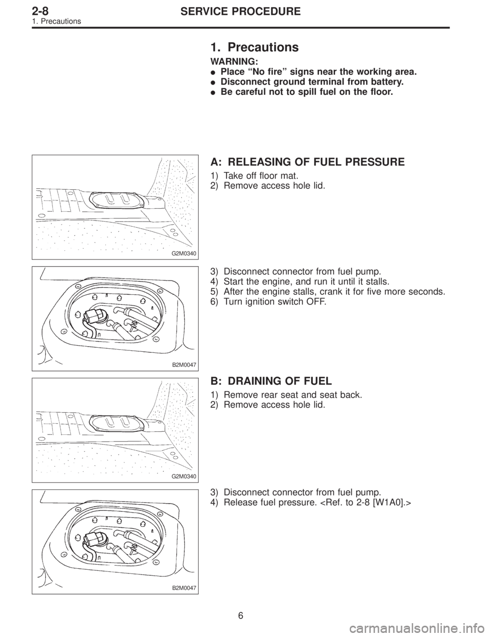
5) Disconnect fuel delivery hose�1and return hose�2.
6) Disconnect jet pump hose�
3. (AWD model)
G2M0343
7) Remove nuts which install fuel pump assembly onto
fuel tank.
G2M0344
8) Take off fuel pump from fuel tank.
G2M0345
9) Drain fuel from fuel tank by using a hand pump.
WARNING:
Do not use a motor pump when draining fuel.
G2M0346
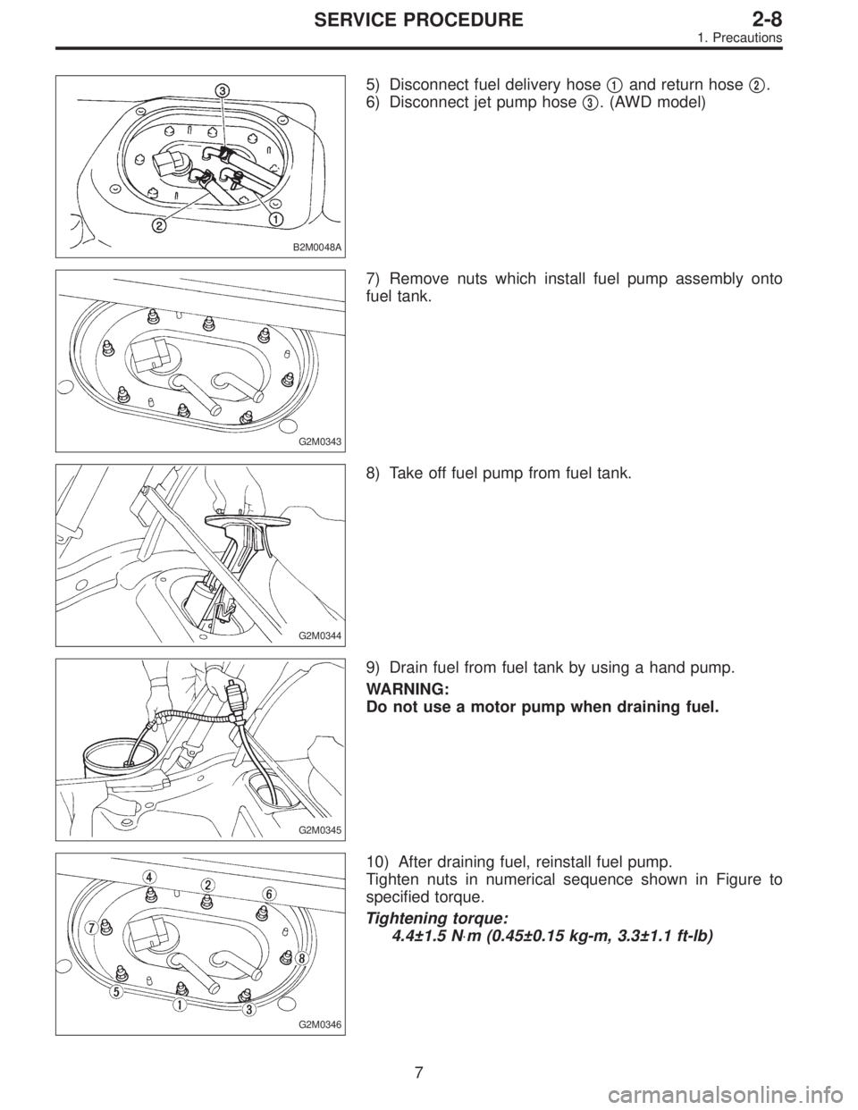
10) After draining fuel, reinstall fuel pump.
Tighten nuts in numerical sequence shown in Figure to
specified torque.
Tightening torque:
4.4±1.5 N⋅m (0.45±0.15 kg-m, 3.3±1.1 ft-lb)
7
2-8SERVICE PROCEDURE
1. Precautions
Page 192 of 2248
B2M0049
11) On AWD model, after removing fuel sub meter unit,
drain fuel from there.
WARNING:
Do not use a motor pump when draining fuel.
2. On-Car Services
A: MEASUREMENT OF FUEL PRESSURE
1) Release fuel pressure.
2) Connect connector to fuel pump.
G2M0347
3) Disconnect fuel delivery hoses from fuel filter, and con-
nect fuel pressure gauge.
G2M0348
4) Start the engine.
5) Measure fuel pressure while disconnecting pressure
regulator vacuum hose from collector chamber.
Fuel pressure:
235 — 265 kPa (2.4 — 2.7 kg/cm
2, 34 — 38 psi)
6) After connecting pressure regulator vacuum hose, mea-
sure fuel pressure.
Fuel pressure:
177 — 206 kPa (1.8 — 2.1 kg/cm
2, 26 — 30 psi)
WARNING:
Before removing fuel pressure gauge, release fuel
pressure.
NOTE:
If out of specification as measured at step 6), check or
replace pressure regulator and pressure regulator vacuum
hose.
8
2-8SERVICE PROCEDURE
1. Precautions - 2. On-Car Services
Page 193 of 2248
B2M0049
11) On AWD model, after removing fuel sub meter unit,
drain fuel from there.
WARNING:
Do not use a motor pump when draining fuel.
2. On-Car Services
A: MEASUREMENT OF FUEL PRESSURE
1) Release fuel pressure.
2) Connect connector to fuel pump.
G2M0347
3) Disconnect fuel delivery hoses from fuel filter, and con-
nect fuel pressure gauge.
G2M0348
4) Start the engine.
5) Measure fuel pressure while disconnecting pressure
regulator vacuum hose from collector chamber.
Fuel pressure:
235 — 265 kPa (2.4 — 2.7 kg/cm
2, 34 — 38 psi)
6) After connecting pressure regulator vacuum hose, mea-
sure fuel pressure.
Fuel pressure:
177 — 206 kPa (1.8 — 2.1 kg/cm
2, 26 — 30 psi)
WARNING:
Before removing fuel pressure gauge, release fuel
pressure.
NOTE:
If out of specification as measured at step 6), check or
replace pressure regulator and pressure regulator vacuum
hose.
8
2-8SERVICE PROCEDURE
1. Precautions - 2. On-Car Services
 Connect oil pressure gauge hose to cylinder block.
5) Start the engine, and measure oil pressure.
Oil pressure:
98 kPa (1.0 kg/cm
2,14 psi) or more at 800 rpm
294 kPa (3.0 kg/cm2, 43 psi) o")
 Disconnect connector from knock sensor.
G2M0416
18) Disconnect connector from camshaft position sensor.
G2M0408
19) Disconnect connector from crankshaft position sensor.
G2M0091
20) Discon")
 On AWD model, after removing fuel sub meter unit,
drain fuel from there.
WARNING:
Do not use a motor pump when draining fuel.
2. On-Car Services
A: MEASUREMENT OF FUEL PRESSURE
1) Release")
 On AWD model, after removing fuel sub meter unit,
drain fuel from there.
WARNING:
Do not use a motor pump when draining fuel.
2. On-Car Services
A: MEASUREMENT OF FUEL PRESSURE
1) Release")