Page 842 of 2248
 or more ...
When 300 m
3(10,593 cu ft)/h�Mode
selector
switch:")
1. Heater System
A: SPECIFICATIONS
ItemSpecifications
Condition
LHD model RHD model
Heating capacity4.652 kW (4,000 kcal/h, 15,872 BTU/h) or more ...
When 300 m
3(10,593 cu ft)/h�Mode
selector
switch: HEAT
�Te m p .
control
lever: FULL HOT
�Temperature
difference
between
hot water
and inlet air:65°C
(149°F)
�Hot water
flow rate: 360�(95.1
US gal, 79.2
Imp gal)/h
Air flow rate 300 m
3(10,593 cu ft)/h 280 m3(9,887 cu ft)/hHeat mode (FRESH), FULL
HOT at 12.5 V
Max air flow rate 510 m
3(18,008 cu ft)/h 480 m3(16,949 cu ft)/h�Temperature
control
lever: FULL COLD
�Blower fan
speed: 4th position
�RECIRC
switch
position: RECIRC
Heater core size
(height x length x width x
thickness)193.5 x 152.0 x 25.0 x 0.9 mm
(7.62 x 5.98 x 0.984 x 0.035 in)159.5 x 180 x 32.0 x 1.0 mm
(6.28 x 7.09 x 1.26 x 0.039 in)—
Blower
motorType Magnet motor 230 W or less Magnet motor 220 W or less at 12 V
Fan type and size
(diameter x width)Sirocco fan type
150 x 75 mm (5.91 x 2.95 in)Sirocco fan type
140 x 65 mm (5.51 x 2.56 in)—
2
4-6SPECIFICATIONS AND SERVICE DATA
1. Heater System
Page 845 of 2248
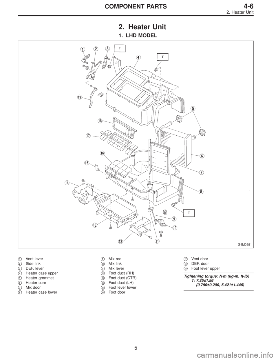
2. Heater Unit
1. LHD MODEL
G4M0551
�1Vent lever
�
2Side link
�
3DEF. lever
�
4Heater case upper
�
5Heater grommet
�
6Heater core
�
7Mix door
�
8Heater case lower�
9Mix rod
�
10Mix link
�
11Mix lever
�
12Foot duct (RH)
�
13Foot duct (CTR)
�
14Foot duct (LH)
�
15Foot lever lower
�
16Foot door�
17Vent door
�
18DEF. door
�
19Foot lever upper
Tightening torque: N⋅m (kg-m, ft-lb)
T: 7.35±1.96
(0.750±0.200, 5.421±1.446)
5
4-6COMPONENT PARTS
2. Heater Unit
Page 846 of 2248
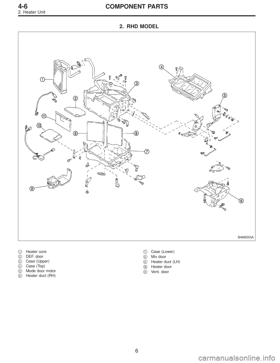
2. RHD MODEL
B4M0055A
�1Heater core
�
2DEF. door
�
3Case (Upper)
�
4Case (Top)
�
5Mode door motor
�
6Heater duct (RH)�
7Case (Lower)
�
8Mix door
�
9Heater duct (LH)
�
10Heater door
�
11Vent. door
6
4-6COMPONENT PARTS
2. Heater Unit
Page 1082 of 2248
G2M0090
5) Remove bolts which install generator onto bracket.
G2M0090
6) Installation is in the reverse order of removal.
CAUTION:
Check and adjust V-belt tension.
B6M0476A
B: DISASSEMBLY
1) Heat the portion�Aof rear cover to 50°C (122°F) with
heater drier.
G6M0065
2) Remove the four through bolts. Then insert the tip of a
flat-head screwdriver into the gap between the stator core
and front bracket. Pry then apart to disassemble.
G6M0066
3) Hold rotor with a vise and remove pulley nut.
16
6-1SERVICE PROCEDURE
2. Generator
![SUBARU LEGACY 1995 Service Repair Manual G2M0090
5) Remove bolts which install generator onto bracket.
G2M0090
6) Installation is in the reverse order of removal.
CAUTION:
Check and adjust V-belt tension. <Ref. to 1-5 [01A0].>
B6M0476A
B: DI](/manual-img/17/57432/w960_57432-1081.png "SUBARU LEGACY 1995 Service Repair Manual G2M0090
5) Remove bolts which install generator onto bracket.
G2M0090
6) Installation is in the reverse order of removal.
CAUTION:
Check and adjust V-belt tension. <Ref. to 1-5 [01A0].>
B6M0476A
B: DI")