Page 20 of 2248
G2M0093
4) Connect oil pressure gauge hose to cylinder block.
5) Start the engine, and measure oil pressure.
Oil pressure:
98 kPa (1.0 kg/cm
2,14 psi) or more at 800 rpm
294 kPa (3.0 kg/cm2, 43 psi) or more at 5,000 rpm
CAUTION:
�If oil pressure is out of specification, check oil
pump, oil filter and lubrication line.
�If oil pressure warning light is turned ON and oil
pressure is in specification, replace oil pressure
switch.
NOTE:
The specified data is based on an engine oil temperature
of 80°C (176°F).
6) After measuring oil pressure, install oil pressure switch.
Tightening torque:
25±3 N⋅m (2.5±0.3 kg-m, 18.1±2.2 ft-lb)
7) Install generator and V-belt in the reverse order of
removal, and adjust the V-belt deflection.
8
2-2
6. Engine Oil Pressure
Page 137 of 2248

1. Engine Cooling System
Trouble Possible cause Corrective action
Over-heatinga. Insufficient engine coolantReplenish engine coolant, inspect for leakage, and
repair.
b. Loose timing belt Repair or replace timing belt tensioner.
c. Oil on drive belt Replace.
d. Malfunction of thermostat Replace.
e. Malfunction of engine coolant pump Replace.
f. Clogged engine coolant passage Clean.
g. Improper ignition timingInspect and repair ignition control system.
h. Clogged or leaking radiator Clean or repair, or replace.
i. Improper engine oil in engine coolant Replace engine coolant.
j. Air/fuel mixture ratio too leanInspect and repair fuel injection system.
k. Excessive back pressure in exhaust system Clean or replace.
l. Insufficient clearance between piston and cylinder Adjust or replace.
m. Slipping clutch Repair or replace.
n. Dragging brake Adjust.
o. Improper transmission oil Replace.
p. Defective thermostat Replace.
q. Malfunction of electric fanInspect radiator fan relay, engine coolant temperature
sensor or radiator motor and replace there.
Over-coolinga. Atmospheric temperature extremely low Partly cover radiator front area.
b. Defective thermostat Replace.
Engine coolant
leaks.a. Loosened or damaged connecting units on hoses Repair or replace.
b. Leakage from engine coolant pump Replace.
c. Leakage from engine coolant pipe Repair or replace.
d. Leakage around cylinder head gasket Retighten cylinder head bolts or replace gasket.
e. Damaged or cracked cylinder head and crankcase Repair or replace.
f. Damaged or cracked thermostat case Repair or replace.
g. Leakage from radiator Repair or replace.
Noisea. Defective drive belt Replace.
b. Defective radiator fan Replace.
c. Defective engine coolant pump bearing Replace engine coolant pump.
d. Defective engine coolant pump mechanical seal Replace engine coolant pump.
19
2-5DIAGNOSTICS
1. Engine Cooling System
Page 165 of 2248
G2M0091
3) Connect connector to oil pressure switch.
G2M0408
4) Connect connector to crankshaft position sensor.
G2M0416
5) Connect connector to camshaft position sensor.
B2M0346
6) Connect connector to knock sensor.
B2M0345A
7) Connect connectors to engine coolant temperature sen-
sor�
1and thermometer�2.
14
2-7SERVICE PROCEDURE
4. Intake Manifold
Page 367 of 2248

G3M0282
2. On-Car Service
A: INSPECTION
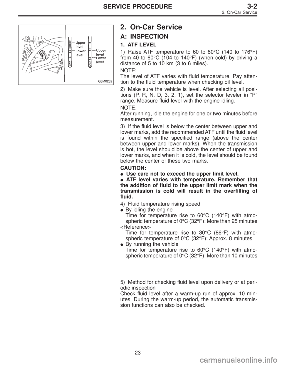
1. ATF LEVEL
1) Raise ATF temperature to 60 to 80°C (140 to 176°F)
from 40 to 60°C (104 to 140°F) (when cold) by driving a
distance of 5 to 10 km (3 to 6 miles).
NOTE:
The level of ATF varies with fluid temperature. Pay atten-
tion to the fluid temperature when checking oil level.
2) Make sure the vehicle is level. After selecting all posi-
tions (P, R, N, D, 3, 2, 1), set the selector leveler in“P”
range. Measure fluid level with the engine idling.
NOTE:
After running, idle the engine for one or two minutes before
measurement.
3) If the fluid level is below the center between upper and
lower marks, add the recommended ATF until the fluid level
is found within the specified range (above the center
between upper and lower marks). When the transmission
is hot, the level should be above the center of upper and
lower marks, and when it is cold, the level should be found
below the center of these two marks.
CAUTION:
�Use care not to exceed the upper limit level.
�ATF level varies with temperature. Remember that
the addition of fluid to the upper limit mark when the
transmission is cold will result in the overfilling of
fluid.
4) Fluid temperature rising speed
�By idling the engine
Time for temperature rise to 60°C (140°F) with atmo-
spheric temperature of 0°C (32°F): More than 25 minutes
Time for temperature rise to 30°C (86°F) with atmo-
spheric temperature of 0°C (32°F): Approx. 8 minutes
�By running the vehicle
Time for temperature rise to 60°C (140°F) with atmo-
spheric temperature of 0°C (32°F): More than 10 minutes
5) Method for checking fluid level upon delivery or at peri-
odic inspection
Check fluid level after a warm-up run of approx. 10 min-
utes. During the warm-up period, the automatic transmis-
sion functions can also be checked.
23
3-2SERVICE PROCEDURE
2. On-Car Service
Page 370 of 2248

G3M0859
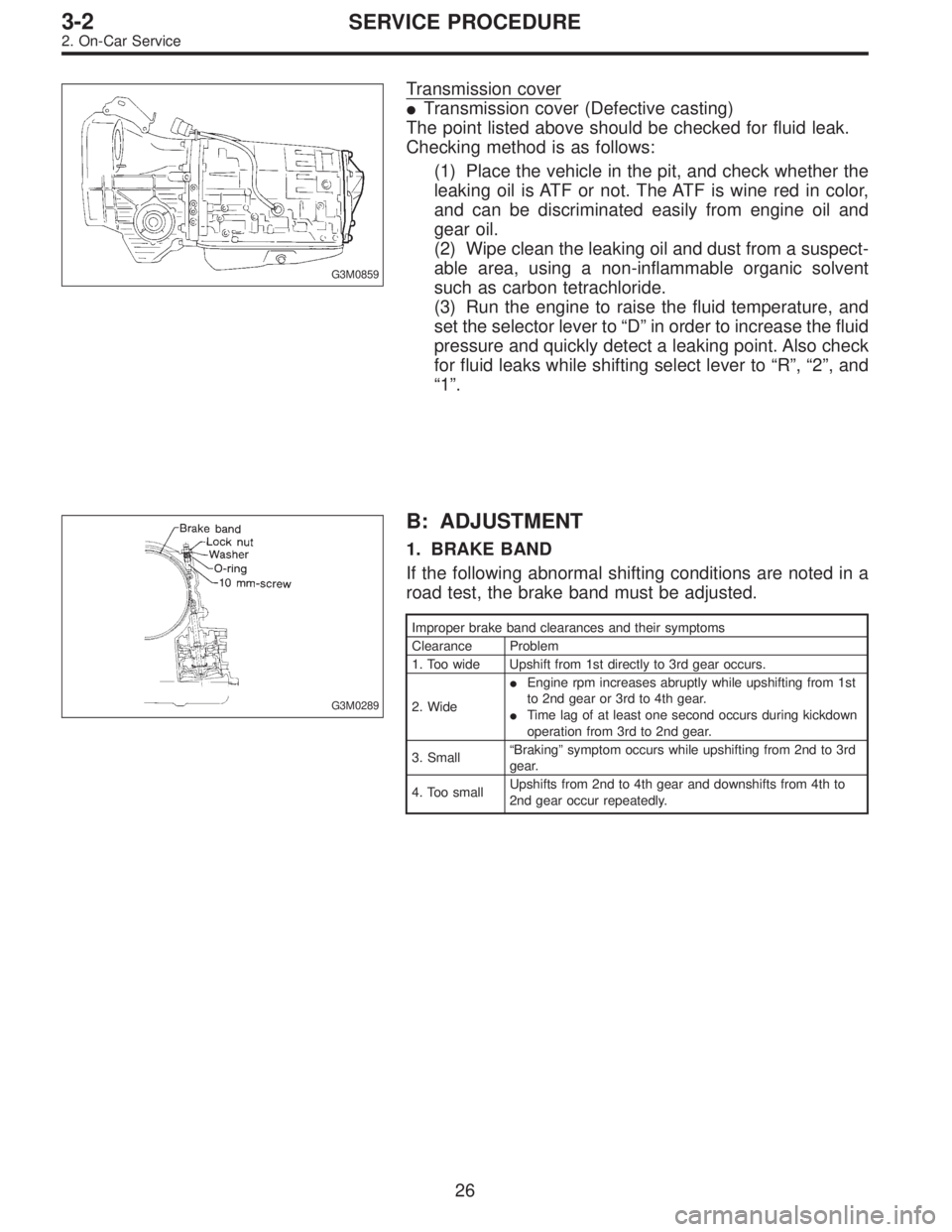
Transmission cover
�Transmission cover (Defective casting)
The point listed above should be checked for fluid leak.
Checking method is as follows:
(1) Place the vehicle in the pit, and check whether the
leaking oil is ATF or not. The ATF is wine red in color,
and can be discriminated easily from engine oil and
gear oil.
(2) Wipe clean the leaking oil and dust from a suspect-
able area, using a non-inflammable organic solvent
such as carbon tetrachloride.
(3) Run the engine to raise the fluid temperature, and
set the selector lever to“D”in order to increase the fluid
pressure and quickly detect a leaking point. Also check
for fluid leaks while shifting select lever to“R”,“2”, and
“1”.
G3M0289
B: ADJUSTMENT
1. BRAKE BAND
If the following abnormal shifting conditions are noted in a
road test, the brake band must be adjusted.
Improper brake band clearances and their symptoms
Clearance Problem
1. Too wide Upshift from 1st directly to 3rd gear occurs.
2. Wide�Engine rpm increases abruptly while upshifting from 1st
to 2nd gear or 3rd to 4th gear.
�Time lag of at least one second occurs during kickdown
operation from 3rd to 2nd gear.
3. Small“Braking”symptom occurs while upshifting from 2nd to 3rd
gear.
4. Too smallUpshifts from 2nd to 4th gear and downshifts from 4th to
2nd gear occur repeatedly.
26
3-2SERVICE PROCEDURE
2. On-Car Service
Page 382 of 2248

3. Performance Test
A: STALL TEST
1. GENERAL
The stall test is of extreme importance in diagnosing the
condition of the automatic transmission and the engine. It
should be conducted to measure the engine stall speeds in
all shift ranges except the P and N ranges.
Purposes of the stall test:
1) To check the operation of the automatic transmission
clutch.
2) To check the operation of the torque converter clutch.
3) To check engine performance.
2. TEST METHODS
Preparations before test:
�
1Check that throttle valve opens fully.
�
2Check that engine oil level is correct.
�
3Check that coolant level is correct.
�
4Check that ATF level is correct.
�
5Check that differential gear oil level is correct.
�
6Increase ATF temperature to 60 to 80°C (140 to 176°F)
by idling the engine for approximately 30 minutes (with
select lever set to“N”or“P”).
1) Install an engine tachometer at a location visible from
the driver’s compartment and mark the stall speed range
on the tachometer scale.
2) Place the wheel chocks at the front and rear of all
wheels and engage the parking brake.
3) Move the manual linkage to ensure it operates properly,
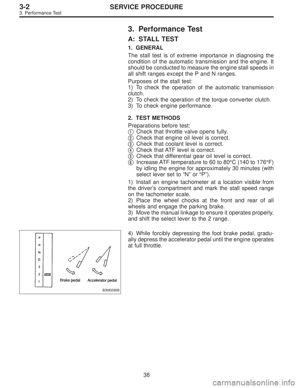
and shift the select lever to the 2 range.
B3M0286B
4) While forcibly depressing the foot brake pedal, gradu-
ally depress the accelerator pedal until the engine operates
at full throttle.
38
3-2SERVICE PROCEDURE
3. Performance Test
Page 385 of 2248

C: LINE PRESSURE TEST
1. GENERAL
If the clutch or the brake band shows a sign of slippage or
shifting sensation is not correct, the line pressure should be
checked.
�Excessive shocks during upshifting or shifting takes
place at a higher point than under normal circumstances,
may be due to the line pressure being too high.
�Slippage or inability to operate the vehicle may, in most
cases, be due to loss of oil pressure for the operation of
the clutch, brake band or control valve.
G3M0869
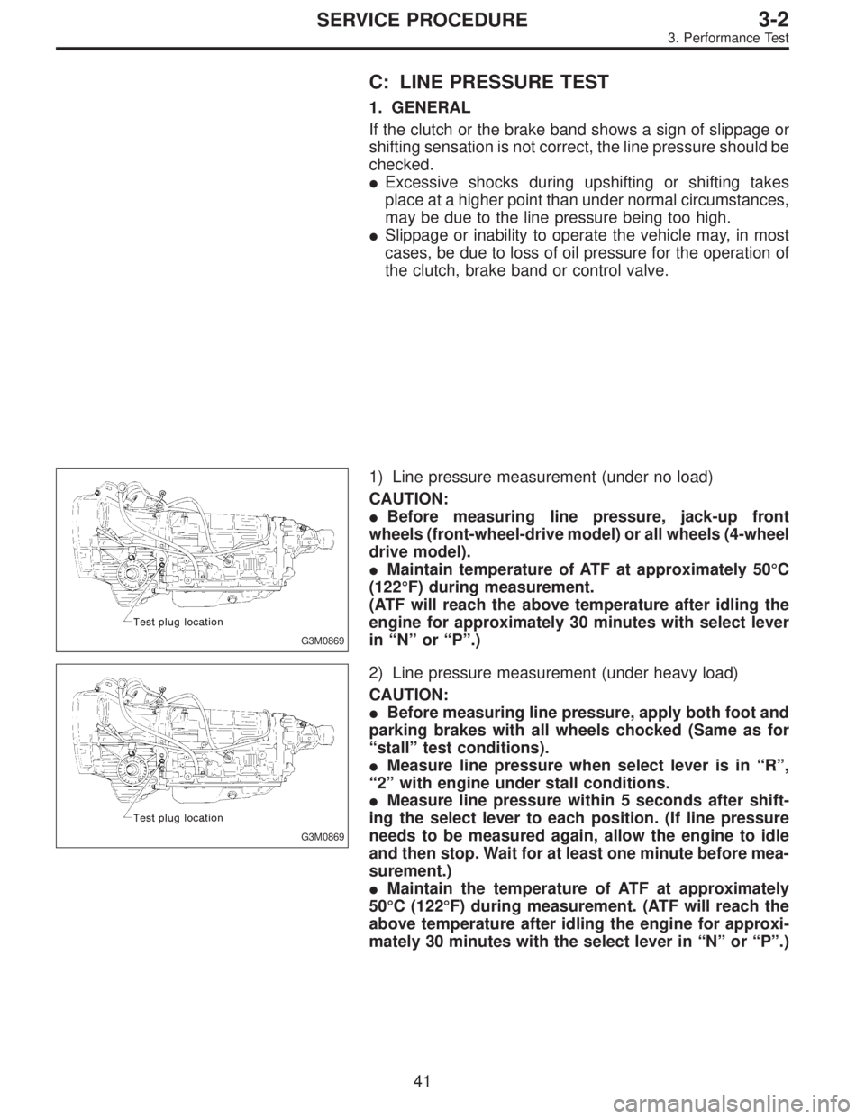
1) Line pressure measurement (under no load)
CAUTION:
�Before measuring line pressure, jack-up front
wheels (front-wheel-drive model) or all wheels (4-wheel
drive model).
�Maintain temperature of ATF at approximately 50°C
(122°F) during measurement.
(ATF will reach the above temperature after idling the
engine for approximately 30 minutes with select lever
in“N”or“P”.)
G3M0869
2) Line pressure measurement (under heavy load)
CAUTION:
�Before measuring line pressure, apply both foot and
parking brakes with all wheels chocked (Same as for
“stall”test conditions).
�Measure line pressure when select lever is in“R”,
“2”with engine under stall conditions.
�Measure line pressure within 5 seconds after shift-
ing the select lever to each position. (If line pressure
needs to be measured again, allow the engine to idle
and then stop. Wait for at least one minute before mea-
surement.)
�Maintain the temperature of ATF at approximately
50°C (122°F) during measurement. (ATF will reach the
above temperature after idling the engine for approxi-
mately 30 minutes with the select lever in“N”or“P”.)
41
3-2SERVICE PROCEDURE
3. Performance Test
Page 419 of 2248
G3M0367
2) Install and route the transmission harness.
CAUTION:
Be careful not to damage the harness.
B3M0418A
3) Install the control valve assembly.
(1) Set the select lever in range“2”.
(2) Install the two brackets, ATF temperature sensor
and the control valve by engaging the manual valve and
manual lever, then tighten the 17 bolts.
Tightening torque:
8±1 N⋅m (0.8±0.1 kg-m, 5.8±0.7 ft-lb)
CAUTION:
�Be careful not to pinch the harness roll the gasket.
�Tighten the control valve mounting bolts evenly.
B3M0419A
4) Install the oil strainer to the control valve. Be careful not
to cut or break the O-ring. Then tighten four bolts.
Tightening torque:
8±1 N⋅m (0.8±0.1 kg-m, 5.8±0.7 ft-lb)
B3M0420A
5) Secure four connectors.
75
3-2SERVICE PROCEDURE
4. Overall Transmission