Page 22 of 2248

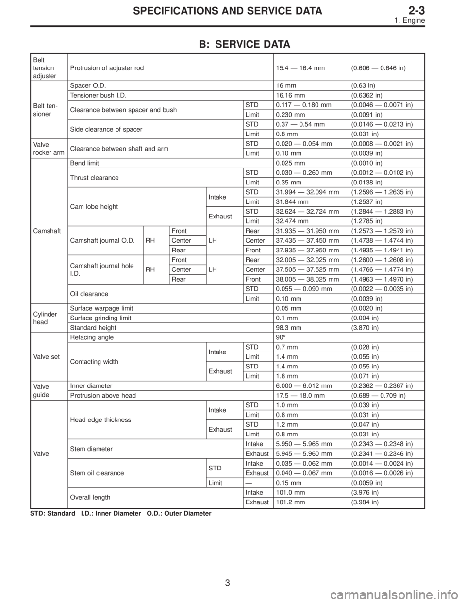
B: SERVICE DATA
Belt
tension
adjusterProtrusion of adjuster rod 15.4—16.4 mm (0.606—0.646 in)
Belt ten-
sionerSpacer O.D. 16 mm (0.63 in)
Tensioner bush I.D. 16.16 mm (0.6362 in)
Clearance between spacer and bushSTD 0.117—0.180 mm (0.0046—0.0071 in)
Limit 0.230 mm (0.0091 in)
Side clearance of spacerSTD 0.37—0.54 mm (0.0146—0.0213 in)
Limit 0.8 mm (0.031 in)
Valve
rocker armClearance between shaft and armSTD 0.020—0.054 mm (0.0008—0.0021 in)
Limit 0.10 mm (0.0039 in)
CamshaftBend limit 0.025 mm (0.0010 in)
Thrust clearanceSTD 0.030—0.260 mm (0.0012—0.0102 in)
Limit 0.35 mm (0.0138 in)
Cam lobe heightIntakeSTD 31.994—32.094 mm (1.2596—1.2635 in)
Limit 31.844 mm (1.2537 in)
ExhaustSTD 32.624—32.724 mm (1.2844—1.2883 in)
Limit 32.474 mm (1.2785 in)
Camshaft journal O.D. RHFront
LHRear 31.935—31.950 mm (1.2573—1.2579 in)
Center Center 37.435—37.450 mm (1.4738—1.4744 in)
Rear Front 37.935—37.950 mm (1.4935—1.4941 in)
Camshaft journal hole
I.D.RHFront
LHRear 32.005—32.025 mm (1.2600—1.2608 in)
Center Center 37.505—37.525 mm (1.4766—1.4774 in)
Rear Front 38.005—38.025 mm (1.4963—1.4970 in)
Oil clearanceSTD 0.055—0.090 mm (0.0022—0.0035 in)
Limit 0.10 mm (0.0039 in)
Cylinder
headSurface warpage limit 0.05 mm (0.0020 in)
Surface grinding limit 0.1 mm (0.004 in)
Standard height 98.3 mm (3.870 in)
Valve setRefacing angle 90°
Contacting widthIntakeSTD 0.7 mm (0.028 in)
Limit 1.4 mm (0.055 in)
ExhaustSTD 1.4 mm (0.055 in)
Limit 1.8 mm (0.071 in)
Valve
guideInner diameter 6.000—6.012 mm (0.2362—0.2367 in)
Protrusion above head 17.5—18.0 mm (0.689—0.709 in)
ValveHead edge thicknessIntakeSTD 1.0 mm (0.039 in)
Limit 0.8 mm (0.031 in)
ExhaustSTD 1.2 mm (0.047 in)
Limit 0.8 mm (0.031 in)
Stem diameterIntake 5.950—5.965 mm (0.2343—0.2348 in)
Exhaust 5.945—5.960 mm (0.2341—0.2346 in)
Stem oil clearanceSTDIntake 0.035—0.062 mm (0.0014—0.0024 in)
Exhaust 0.040—0.067 mm (0.0016—0.0026 in)
Limit—0.15 mm (0.0059 in)
Overall lengthIntake 101.0 mm (3.976 in)
Exhaust 101.2 mm (3.984 in)
STD: Standard I.D.: Inner Diameter O.D.: Outer Diameter
3
2-3SPECIFICATIONS AND SERVICE DATA
1. Engine
Page 23 of 2248

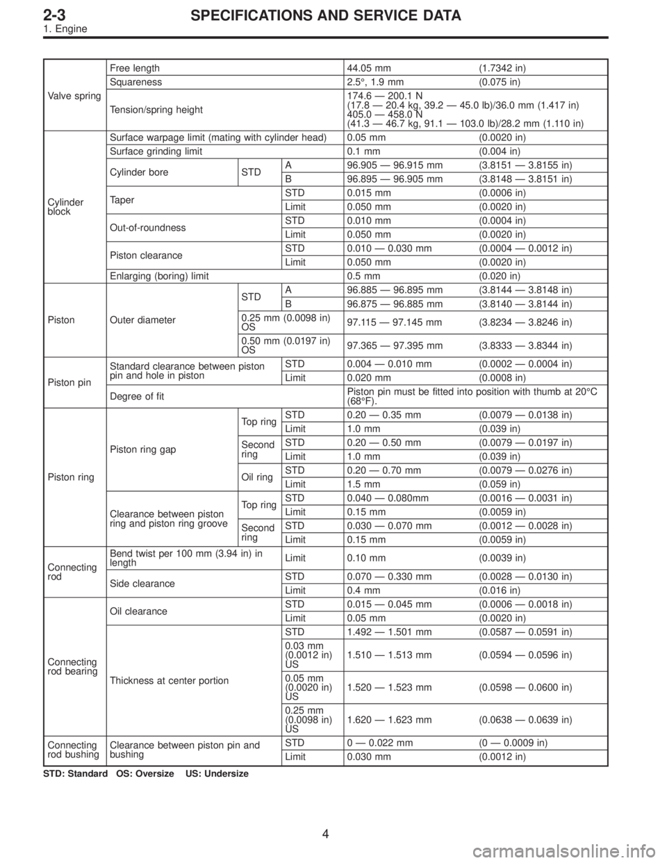
Valve springFree length 44.05 mm (1.7342 in)
Squareness 2.5°, 1.9 mm (0.075 in)
Tension/spring height174.6—200.1 N
(17.8—20.4 kg, 39.2—45.0 lb)/36.0 mm (1.417 in)
405.0—458.0 N
(41.3—46.7 kg, 91.1—103.0 lb)/28.2 mm (1.110 in)
Cylinder
blockSurface warpage limit (mating with cylinder head) 0.05 mm (0.0020 in)
Surface grinding limit 0.1 mm (0.004 in)
Cylinder bore STDA 96.905—96.915 mm (3.8151—3.8155 in)
B 96.895—96.905 mm (3.8148—3.8151 in)
TaperSTD 0.015 mm (0.0006 in)
Limit 0.050 mm (0.0020 in)
Out-of-roundnessSTD 0.010 mm (0.0004 in)
Limit 0.050 mm (0.0020 in)
Piston clearanceSTD 0.010—0.030 mm (0.0004—0.0012 in)
Limit 0.050 mm (0.0020 in)
Enlarging (boring) limit 0.5 mm (0.020 in)
Piston Outer diameterSTDA 96.885—96.895 mm (3.8144—3.8148 in)
B 96.875—96.885 mm (3.8140—3.8144 in)
0.25 mm (0.0098 in)
OS97.115—97.145 mm (3.8234—3.8246 in)
0.50 mm (0.0197 in)
OS97.365—97.395 mm (3.8333—3.8344 in)
Piston pinStandard clearance between piston
pin and hole in pistonSTD 0.004—0.010 mm (0.0002—0.0004 in)
Limit 0.020 mm (0.0008 in)
Degree of fitPiston pin must be fitted into position with thumb at 20°C
(68°F).
Piston ringPiston ring gapTop ringSTD 0.20—0.35 mm (0.0079—0.0138 in)
Limit 1.0 mm (0.039 in)
Second
ringSTD 0.20—0.50 mm (0.0079—0.0197 in)
Limit 1.0 mm (0.039 in)
Oil ringSTD 0.20—0.70 mm (0.0079—0.0276 in)
Limit 1.5 mm (0.059 in)
Clearance between piston
ring and piston ring grooveTop ringSTD 0.040—0.080mm (0.0016—0.0031 in)
Limit 0.15 mm (0.0059 in)
Second
ringSTD 0.030—0.070 mm (0.0012—0.0028 in)
Limit 0.15 mm (0.0059 in)
Connecting
rodBend twist per 100 mm (3.94 in) in
lengthLimit 0.10 mm (0.0039 in)
Side clearanceSTD 0.070—0.330 mm (0.0028—0.0130 in)
Limit 0.4 mm (0.016 in)
Connecting
rod bearingOil clearanceSTD 0.015—0.045 mm (0.0006—0.0018 in)
Limit 0.05 mm (0.0020 in)
Thickness at center portionSTD 1.492—1.501 mm (0.0587—0.0591 in)
0.03 mm
(0.0012 in)
US1.510—1.513 mm (0.0594—0.0596 in)
0.05 mm
(0.0020 in)
US1.520—1.523 mm (0.0598—0.0600 in)
0.25 mm
(0.0098 in)
US1.620—1.623 mm (0.0638—0.0639 in)
Connecting
rod bushingClearance between piston pin and
bushingSTD 0—0.022 mm (0—0.0009 in)
Limit 0.030 mm (0.0012 in)
STD: Standard OS: Oversize US: Undersize
4
2-3SPECIFICATIONS AND SERVICE DATA
1. Engine
Page 37 of 2248
G2M0111
(2) Using white paint, put alignment and/or arrow
marks on timing belts in relation to the sprockets.
Z
1: 44 tooth length
Z
2: 40.5 tooth length
B2M0065
2) Loosen tensioner adjuster mounting bolts.
3) Remove belt idler.
4) Remove belt idler No. 2.
5) Remove timing belt.
6) Remove tensioner adjuster.
17
2-3SERVICE PROCEDURE
3. Timing Belt
Page 65 of 2248

G2M0153
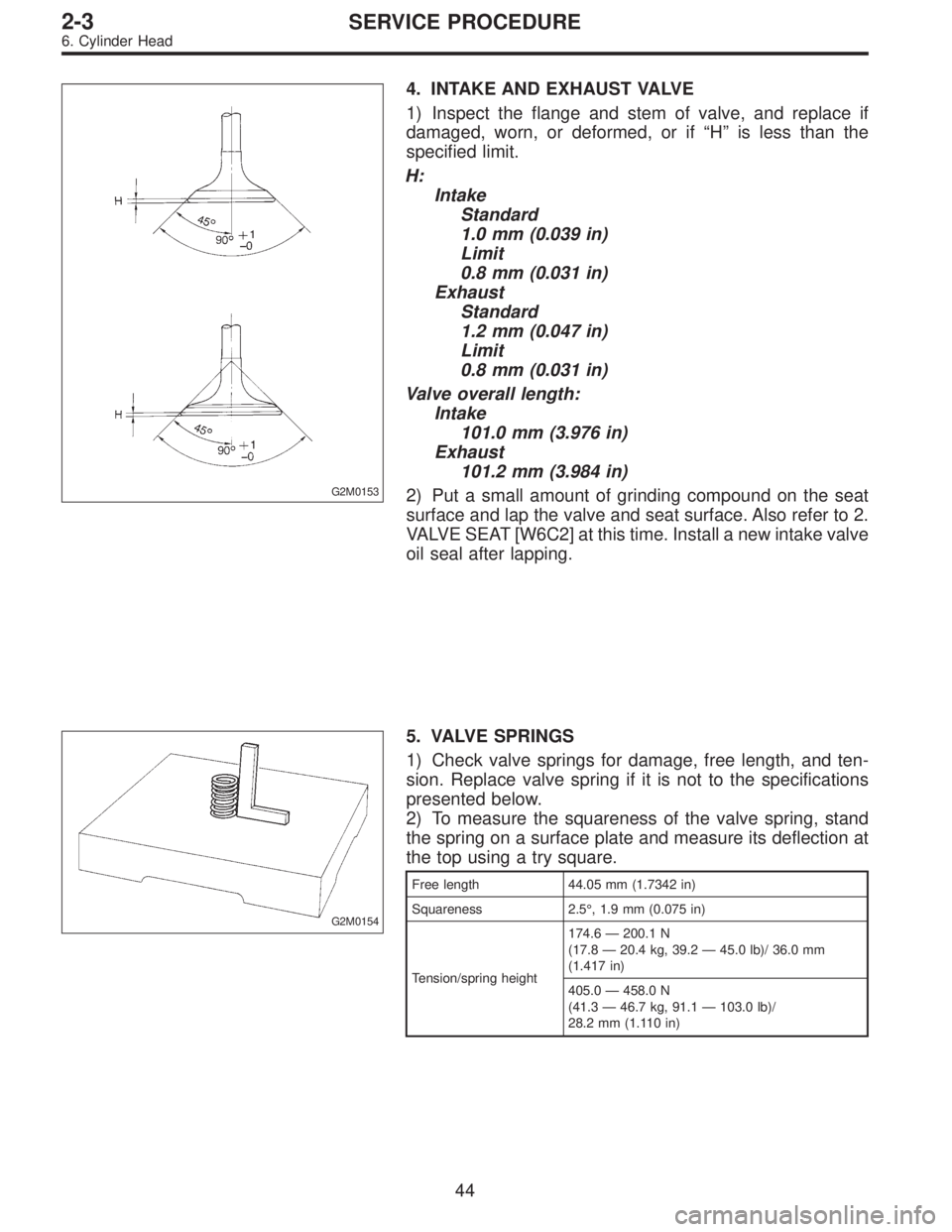
4. INTAKE AND EXHAUST VALVE
1) Inspect the flange and stem of valve, and replace if
damaged, worn, or deformed, or if“H”is less than the
specified limit.
H:
Intake
Standard
1.0 mm (0.039 in)
Limit
0.8 mm (0.031 in)
Exhaust
Standard
1.2 mm (0.047 in)
Limit
0.8 mm (0.031 in)
Valve overall length:
Intake
101.0 mm (3.976 in)
Exhaust
101.2 mm (3.984 in)
2) Put a small amount of grinding compound on the seat
surface and lap the valve and seat surface. Also refer to 2.
VALVE SEAT [W6C2] at this time. Install a new intake valve
oil seal after lapping.
G2M0154
5. VALVE SPRINGS
1) Check valve springs for damage, free length, and ten-
sion. Replace valve spring if it is not to the specifications
presented below.
2) To measure the squareness of the valve spring, stand
the spring on a surface plate and measure its deflection at
the top using a try square.
Free length 44.05 mm (1.7342 in)
Squareness 2.5°, 1.9 mm (0.075 in)
Tension/spring height174.6—200.1 N
(17.8—20.4 kg, 39.2—45.0 lb)/ 36.0 mm
(1.417 in)
405.0—458.0 N
(41.3—46.7 kg, 91.1—103.0 lb)/
28.2 mm (1.110 in)
44
2-3SERVICE PROCEDURE
6. Cylinder Head
Page 81 of 2248
G2M0175
3) Measure the clearance between piston ring and piston
ring groove with a thickness gauge.
CAUTION:
Before measuring the clearance, clean the piston ring
groove and piston ring.
Unit: mm (in)
Standard Limit
Clearance
between piston
ring and piston
ring grooveTop ring0.040—0.080
(0.0016—
0.0031)0.15 (0.0059)
Second ring0.030—0.070
(0.0012—
0.0028)0.15 (0.0059)
5. CONNECTING ROD
1) Replace connecting rod, if the large or small end thrust
surface is damaged.
G2M0196
2) Check for bend or twist using a connecting rod aligner.
Replace connecting rod if the bend or twist exceeds the
limit.
Limit of bend or twist per 100 mm (3.94 in) in length:
0.10 mm (0.0039 in)
�
1Thickness gauge
�
2Connecting rod
60
2-3SERVICE PROCEDURE
7. Cylinder Block
Page 105 of 2248
B2M0318
3. SIDE CLEARANCE
Measure clearance between oil pump inner rotor and pump
cover. If the clearance exceeds the limit, replace rotor or
pump body.
Side clearance:
Standard
0.02—0.07 mm (0.0008—0.0028 in)
Limit
0.15 mm (0.0059 in)
4. OIL RELIEF VALVE
Check the valve for fitting condition and damage, and the
relief valve spring for damage and deterioration. Replace
the parts if defective.
Relief valve spring:
Free length; 71.8 mm (2.827 in)
Installed length; 54.7 mm (2.154 in)
Load when installed; 77.08 N (7.86 kg, 17.33 lb)
5. OIL PUMP CASE
Check the oil pump case for worn shaft hole, clogged oil
passage, worn rotor chamber, cracks, and other faults.
6. OIL SEAL
Check the oil seal lips for deformation, hardening, wear,
etc. and replace if defective.
G2M0076
D: ASSEMBLY
1) Install front oil seal by using ST.
ST 499587100 OIL SEAL INSTALLER
CAUTION:
Use a new oil seal.
6
2-4SERVICE PROCEDURE
1. Oil Pump
Page 196 of 2248
G2M0357
3) Install hose and hold down clips at positions indicated
in Figure.
Tightening torque:
1.0
+0.5
�0N⋅m (0.1+0.05
�0kg-m, 0.7+0.4
�0ft-lb)
Type A: When fitting length is specified.
Type B: When fitting length is not specified.
�
1Fitting
�
2Clamp
�
3Hose
�: 1.0 — 4.0 mm (0.039 — 0.157 in)
L: 20 — 25 mm (0.79 — 0.98 in)
G2M0358
�1Hose
�
2Clip
�
3Pipe
Fuel return hose:
L = 20 — 25 mm (0.79 — 0.98 in)
Evaporation hose:
L = 15 — 20 mm (0.59 — 0.79 in)
G2M0356
4) Tighten band mounting bolts.
Tightening torque:
33±10 N⋅m (3.4±1.0 kg-m, 25±7 ft-lb)
G4M0545
5) Install rear crossmember.
11
2-8SERVICE PROCEDURE
3. Fuel Tank
Page 208 of 2248
G2M0296
4) In engine compartment, detach fuel delivery hose,
return hose and evaporation hose.
G2M0370
5) In engine compartment, detach canister hoses from
canister.
G2M0357
B: INSTALLATION
Installation is in the reverse order of removal.
1) Connect fuel delivery hose to pipe with an overlap of 20
to 25 mm (0.79 to 0.98 in).
Type A: When fitting length is specified.
Type B: When fitting length is not specified.
�
1Fitting
�
2Clamp
�
3Hose
�: 1.0—4.0 mm (0.039—0.157 in)
L: 20—25 mm (0.79—0.98 in)
G2M0358
2) Connect evaporation hose to pipe by approx. 15 mm
(0.59 in) from hose end.
�
1Hose
�
2Clip
�
3Pipe
L=15—20 mm (0.59—0.79 in)
CAUTION:
Be sure to inspect hoses and their connections for any
leakage of fuel.
19
2-8SERVICE PROCEDURE
8. Fuel Delivery, Return and Evaporation Lines