Page 160 of 2248
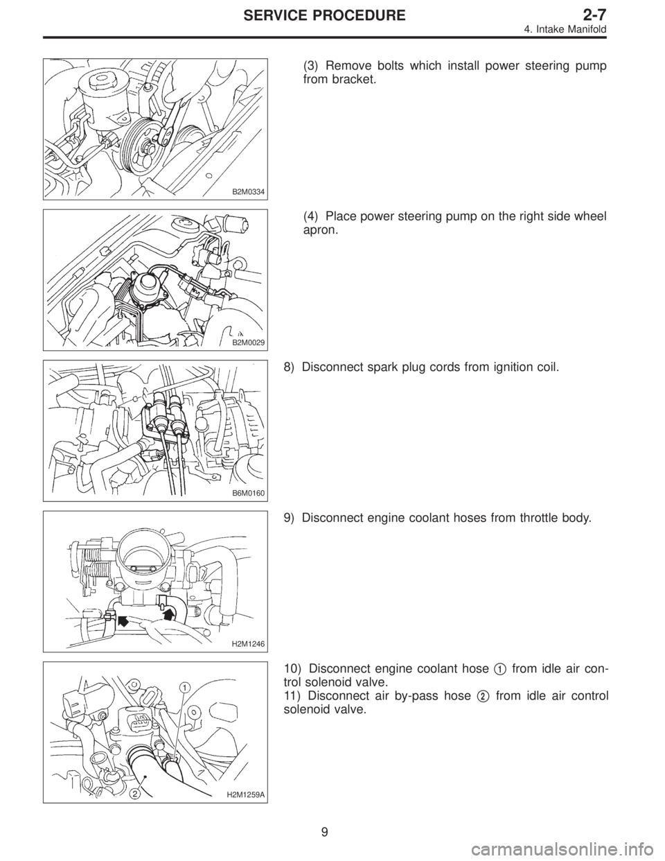
B2M0334
(3) Remove bolts which install power steering pump
from bracket.
B2M0029
(4) Place power steering pump on the right side wheel
apron.
B6M0160
8) Disconnect spark plug cords from ignition coil.
H2M1246
9) Disconnect engine coolant hoses from throttle body.
H2M1259A
10) Disconnect engine coolant hose�1from idle air con-
trol solenoid valve.
11) Disconnect air by-pass hose�
2from idle air control
solenoid valve.
9
2-7SERVICE PROCEDURE
4. Intake Manifold
Page 248 of 2248
G2M0286
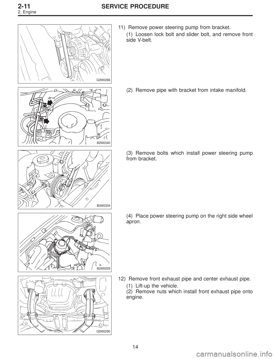
11) Remove power steering pump from bracket.
(1) Loosen lock bolt and slider bolt, and remove front
side V-belt.
B2M0340
(2) Remove pipe with bracket from intake manifold.
B2M0334
(3) Remove bolts which install power steering pump
from bracket.
B2M0029
(4) Place power steering pump on the right side wheel
apron.
G2M0290
12) Remove front exhaust pipe and center exhaust pipe.
(1) Lift-up the vehicle.
(2) Remove nuts which install front exhaust pipe onto
engine.
14
2-11SERVICE PROCEDURE
2. Engine
Page 388 of 2248
4. CHECK FOR THE AWD FUNCTION
If“tight-corner braking”occurs when the steering wheel is
fully turned at low speed:
1) Determine the applicable trouble code and check the
corresponding duty solenoid C (transfer) for improper
operation.
2) If the solenoid is operating properly, check transfer
clutch pressure.
3) If oil pressure is normal but“tight-corner braking”
occurs:
Check the transfer control valve for sticking, and the trans-
fer clutch facing for wear.
44
3-2SERVICE PROCEDURE
3. Performance Test
Page 523 of 2248
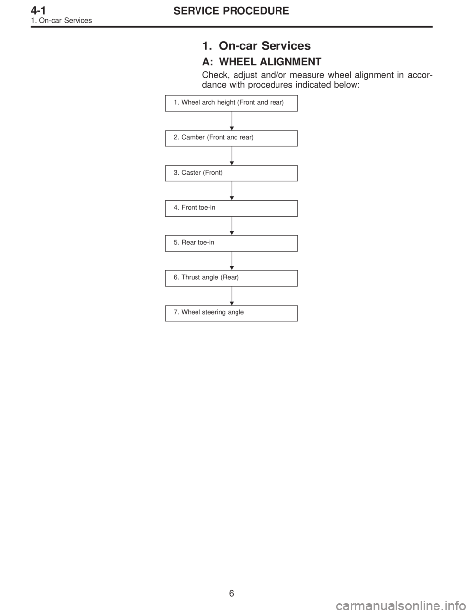
1. On-car Services
A: WHEEL ALIGNMENT
Check, adjust and/or measure wheel alignment in accor-
dance with procedures indicated below:
1. Wheel arch height (Front and rear)
2. Camber (Front and rear)
3. Caster (Front)
4. Front toe-in
5. Rear toe-in
6. Thrust angle (Rear)
7. Wheel steering angle
�
�
�
�
�
�
6
4-1SERVICE PROCEDURE
1. On-car Services
Page 524 of 2248
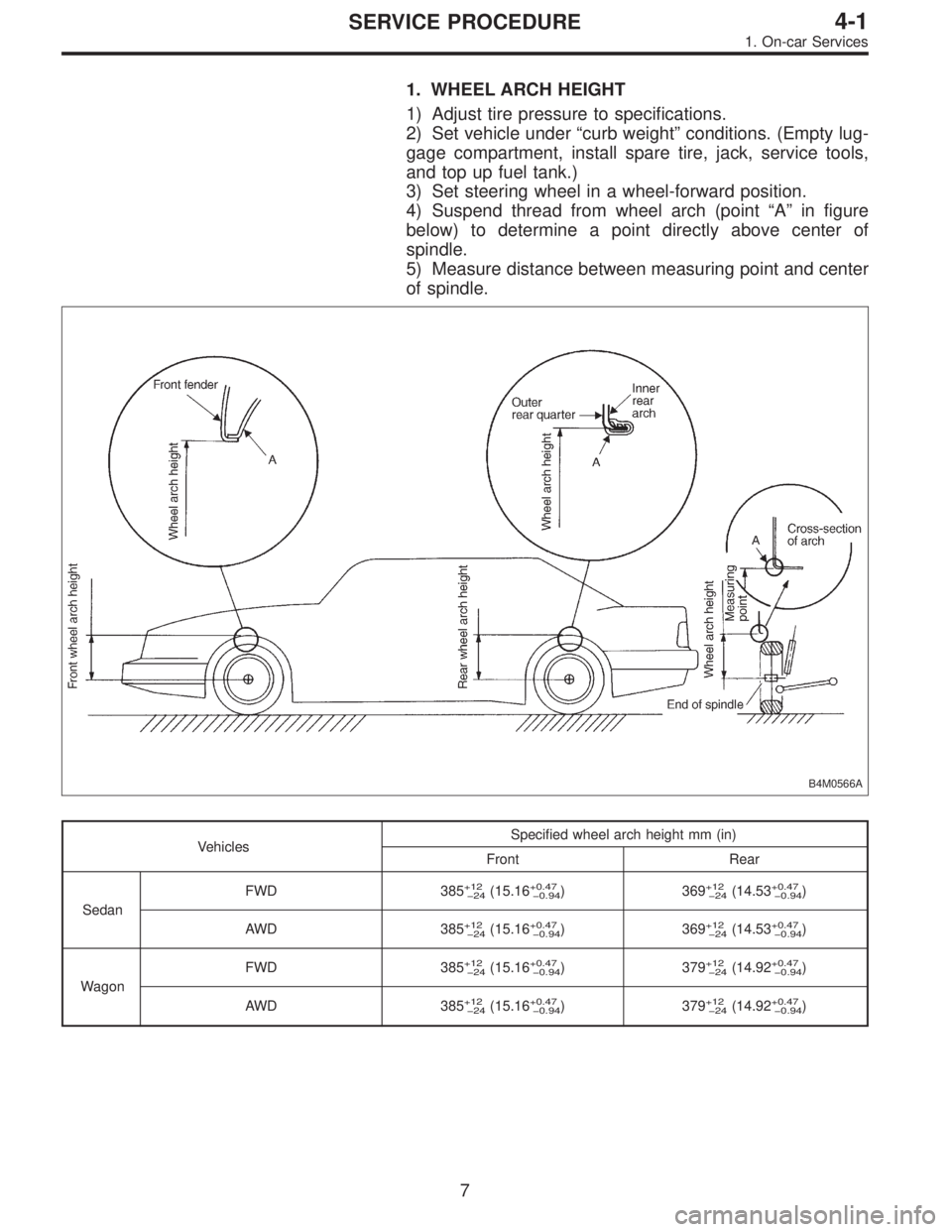
1. WHEEL ARCH HEIGHT
1) Adjust tire pressure to specifications.
2) Set vehicle under“curb weight”conditions. (Empty lug-
gage compartment, install spare tire, jack, service tools,
and top up fuel tank.)
3) Set steering wheel in a wheel-forward position.
4) Suspend thread from wheel arch (point“A”in figure
below) to determine a point directly above center of
spindle.
5) Measure distance between measuring point and center
of spindle.
B4M0566A
VehiclesSpecified wheel arch height mm (in)
Front Rear
SedanFWD 385
+12
24(15.16+0.47
0.94) 369+12
24(14.53+0.47
0.94)
AWD 385
+12
24(15.16+0.47
0.94) 369+12
24(14.53+0.47
0.94)
WagonFWD 385
+12
24(15.16+0.47
0.94) 379+12
24(14.92+0.47
0.94)
AWD 385
+12
24(15.16+0.47
0.94) 379+12
24(14.92+0.47
0.94)
7
4-1SERVICE PROCEDURE
1. On-car Services
Page 527 of 2248
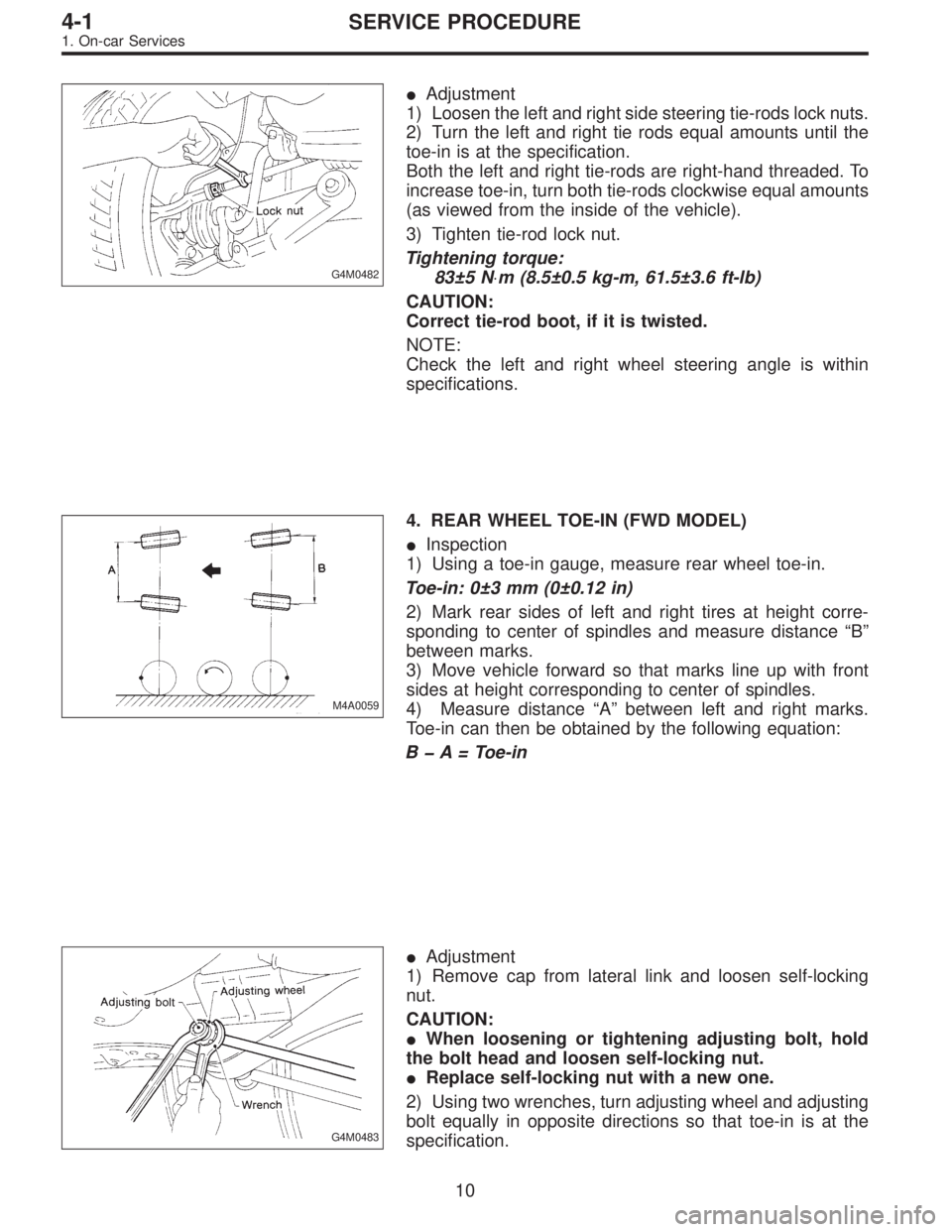
G4M0482
�Adjustment
1) Loosen the left and right side steering tie-rods lock nuts.
2) Turn the left and right tie rods equal amounts until the
toe-in is at the specification.
Both the left and right tie-rods are right-hand threaded. To
increase toe-in, turn both tie-rods clockwise equal amounts
(as viewed from the inside of the vehicle).
3) Tighten tie-rod lock nut.
Tightening torque:
83±5 N⋅m (8.5±0.5 kg-m, 61.5±3.6 ft-lb)
CAUTION:
Correct tie-rod boot, if it is twisted.
NOTE:
Check the left and right wheel steering angle is within
specifications.
M4A0059
4. REAR WHEEL TOE-IN (FWD MODEL)
�Inspection
1) Using a toe-in gauge, measure rear wheel toe-in.
Toe-in: 0±3 mm (0±0.12 in)
2) Mark rear sides of left and right tires at height corre-
sponding to center of spindles and measure distance“B”
between marks.
3) Move vehicle forward so that marks line up with front
sides at height corresponding to center of spindles.
4) Measure distance“A”between left and right marks.
Toe-in can then be obtained by the following equation:
BA = Toe-in
G4M0483
�Adjustment
1) Remove cap from lateral link and loosen self-locking
nut.
CAUTION:
�When loosening or tightening adjusting bolt, hold
the bolt head and loosen self-locking nut.
�Replace self-locking nut with a new one.
2) Using two wrenches, turn adjusting wheel and adjusting
bolt equally in opposite directions so that toe-in is at the
specification.
10
4-1SERVICE PROCEDURE
1. On-car Services
Page 531 of 2248
7. STEERING ANGLE
�Inspection
1) Place vehicle on a turning radius gauge.
2) While depressing brake pedal, turn steering wheel fully
to the left and right. With steering wheel held at each fully
turned position, measure both the inner and outer wheel
steering angle.
Steering angle:
Inner wheel 37.6°±1.5°
Outer wheel 32.6°±1.5°
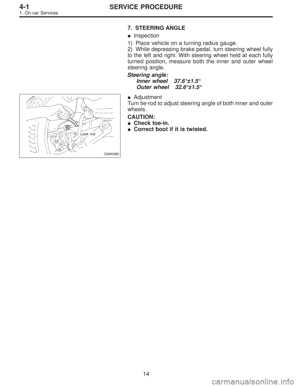
G4M0482
�Adjustment
Turn tie-rod to adjust steering angle of both inner and outer
wheels.
CAUTION:
�Check toe-in.
�Correct boot if it is twisted.
14
4-1SERVICE PROCEDURE
1. On-car Services
Page 544 of 2248
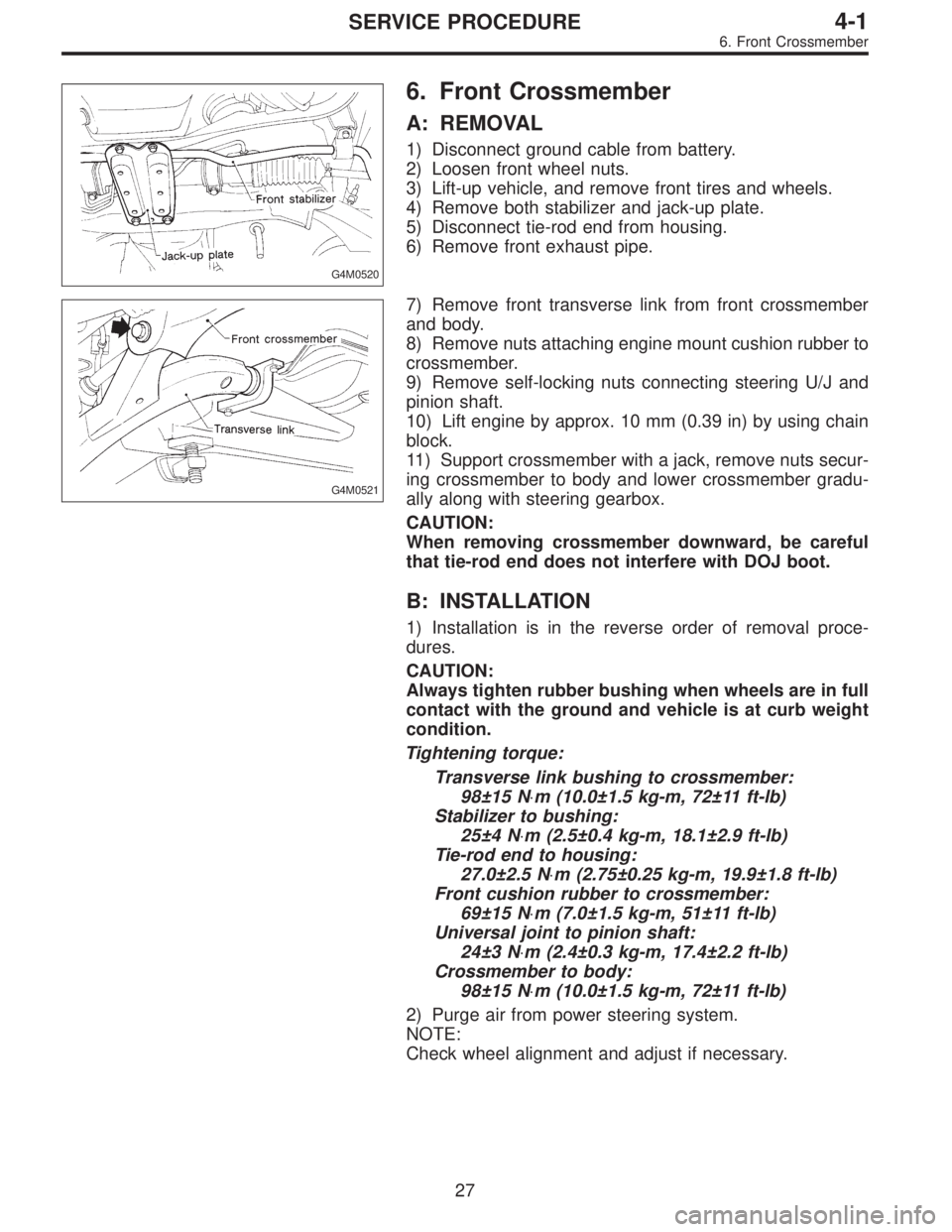
G4M0520
6. Front Crossmember
A: REMOVAL
1) Disconnect ground cable from battery.
2) Loosen front wheel nuts.
3) Lift-up vehicle, and remove front tires and wheels.
4) Remove both stabilizer and jack-up plate.
5) Disconnect tie-rod end from housing.
6) Remove front exhaust pipe.
G4M0521
7) Remove front transverse link from front crossmember
and body.
8) Remove nuts attaching engine mount cushion rubber to
crossmember.
9) Remove self-locking nuts connecting steering U/J and
pinion shaft.
10) Lift engine by approx. 10 mm (0.39 in) by using chain
block.
11) Support crossmember with a jack, remove nuts secur-
ing crossmember to body and lower crossmember gradu-
ally along with steering gearbox.
CAUTION:
When removing crossmember downward, be careful
that tie-rod end does not interfere with DOJ boot.
B: INSTALLATION
1) Installation is in the reverse order of removal proce-
dures.
CAUTION:
Always tighten rubber bushing when wheels are in full
contact with the ground and vehicle is at curb weight
condition.
Tightening torque:
Transverse link bushing to crossmember:
98±15 N⋅m (10.0±1.5 kg-m, 72±11 ft-lb)
Stabilizer to bushing:
25±4 N⋅m (2.5±0.4 kg-m, 18.1±2.9 ft-lb)
Tie-rod end to housing:
27.0±2.5 N⋅m (2.75±0.25 kg-m, 19.9±1.8 ft-lb)
Front cushion rubber to crossmember:
69±15 N⋅m (7.0±1.5 kg-m, 51±11 ft-lb)
Universal joint to pinion shaft:
24±3 N⋅m (2.4±0.3 kg-m, 17.4±2.2 ft-lb)
Crossmember to body:
98±15 N⋅m (10.0±1.5 kg-m, 72±11 ft-lb)
2) Purge air from power steering system.
NOTE:
Check wheel alignment and adjust if necessary.
27
4-1SERVICE PROCEDURE
6. Front Crossmember