Page 853 of 2248
7) Installation is in the reverse order of removal.
Fitted length of heater hose over pipe:
25 — 30 mm (0.98 — 1.18 in)
8) Pour coolant.
B5M0025
3. Blower Motor Assembly
A: REMOVAL AND INSTALLATION
1) Disconnect GND cable from battery.
2) Remove glove box and pocket back panel.
[W1A0].>
3) Disconnect blower motor harness connector.
G4M0555
4) Disconnect aspirator pipe�1.
5) Remove blower motor mounting screw.
6) Remove blower motor assembly.
7) Installation is in the reverse order of removal.
12
4-6SERVICE PROCEDURE
2. Heater Unit - 3. Blower Motor Assembly
Page 854 of 2248
7) Installation is in the reverse order of removal.
Fitted length of heater hose over pipe:
25 — 30 mm (0.98 — 1.18 in)
8) Pour coolant.
B5M0025
3. Blower Motor Assembly
A: REMOVAL AND INSTALLATION
1) Disconnect GND cable from battery.
2) Remove glove box and pocket back panel.
[W1A0].>
3) Disconnect blower motor harness connector.
G4M0555
4) Disconnect aspirator pipe�1.
5) Remove blower motor mounting screw.
6) Remove blower motor assembly.
7) Installation is in the reverse order of removal.
12
4-6SERVICE PROCEDURE
2. Heater Unit - 3. Blower Motor Assembly
Page 883 of 2248
 The A/C system to be tested must have an adequate
refrigerant charge to begin with.
2) The are")
8. Leak Testing
The following points should be kept in mind when conduct-
ing a refrigerant leak test.
1) The A/C system to be tested must have an adequate
refrigerant charge to begin with.
2) The area where the leak test is conducted must be free
of wind and drafts, with still air being the ideal condition.
3) The atmosphere where the leak test is conducted must
be free of refrigerant contamination.
4) Operate the A/C system for approx. 10 minutes, then
turn the engine off an begin the leak test.
5) Refrigerant gas is heavier than air, therefore always
hold the probe below the connection being tested.
6) When checking for a leak along a length of hose or
tube, the leak detector probe must be moved slowly,
approx. 25 mm (1 in) per second making sure probe does
not come in contact with the component being tested.
7) When checking for a leak at a certain point, the leak
detector probe must be held at that point for at least 5
seconds.
G4M0609
1. CHECK THE SYSTEM PRESSURE
With gauges connected to the A/C system, operate the A/C
and confirm that the high side pressure is above 690 kPa
(7.03 kg/cm
2, 100 psi). If not, evacuate and charge the
system before leak checking (refer to evacuation and
charging sections).
2. CLEAN CONNECTIONS BEFORE TESTING
Before testing, use a clean shop towel to wipe off refriger-
ant oil, dirt, or foreign material from all of the connections
and components to be tested.
NOTE:
Since refrigerant oil absorbs refrigerant, excess oil on or
near a connection may falsely signal a leak.
B4M0089
3. CALIBRATE LEAK DETECTOR
Refer to the manufacturer’s instructions for the particular
type of detector used and calibrate the instrument.
CAUTION:
Always make sure that the probe tip filter is clean and
free of contamination.
23
4-7SERVICE PROCEDURE
8. Leak Testing
Page 885 of 2248
 Begin at the connection of the low-pressure tube to the
evaporator, and work your way along the low-pressure of
the system to the compressor. There are thre")
G4M0615
5. LEAK TEST—LOW-PRESSURE SIDE
1) Begin at the connection of the low-pressure tube to the
evaporator, and work your way along the low-pressure of
the system to the compressor. There are three places to
check on each tube connection.
2) Check the area.
(1) Check the area where the fitting joins the tube.
(2) Check the area where the two parts of the fitting
join each other.
G4M0616
(3) Check the area where the nut joins the tube.
G4M0617
6. CHECK THE FLEXIBLE HOSES
Visually inspect the rubber portions of the flexible hoses for
cracking. Probe the rubber section, including the ends of
any insulators or protectors which may cover sections of
the rubber hose, and near the ends where the rubber
meets the metal collar.
NOTE:
Be certain to move the probe slowly [approximately 25 mm
(1 in) per second] when probing along any length of hose
or tube.
G4M0618
7. CHECK THE EVAPORATOR ASSEMBLY
1) Use one or both of the following methods to check the
evaporator assembly.
2) Remove the drain hose from the case drain nipple. Hold
the probe at the end of the case drain nipple for at least 10
seconds. Be certain to reconnect the drain hose when fin-
ished.
3) With the ignition key in the“ACC”position, run the
blower on high speed for 1 minute, then turn the blower off.
Place the probe in the center instrument panel vent, an turn
the blower on low speed for 1 to 2 seconds, then turn the
blower off. Leave the probe in the vent for at least 10 sec-
onds.
25
4-7SERVICE PROCEDURE
8. Leak Testing
Page 949 of 2248
 beyond
radiator panel, make sure that:
�No clearance exists between buffe")
G5M0141
C: INSTALLATION
Installation is in the reverse order of removal.
CAUTION:
With buffer protruding about 18 mm (0.71 in) beyond
radiator panel, make sure that:
�No clearance exists between buffer and inner hood.
�Hood main lock is applied when hood is released at
a height of approximately 10 cm (3.94 in) above the
closed position.
G5M0142
NOTE:
�Align the center of striker with lock during installation.
Make sure safety lever is properly caught by striker under
the hood’s own weight.
�Route hood lock release cable and hold with clips.
�After installing release cable, ensure it operates
smoothly.
�Apply grease to sliding surfaces of parts.
B5M0268A
D: ADJUSTMENT
1) Fore-aft and left-right adjustments
Loosen striker mounting bolts and adjust fore-and-aft posi-
tion of striker.
CAUTION:
Do not adjust striker position using the lock. Doing so
may result in a misaligned front grille.
2) Up-down adjustment
Make up-and-down adjustment of striker only when hood
does not properly contact buffer or hood is not flush with
fender, or when release cable does not properly operate.
Adjustment can be made by adjusting the stroke length of
striker after lock assembly mounting screws are removed.
32
5-1SERVICE PROCEDURE
1. Hood
Page 959 of 2248

3. DEEP DAMAGE SUCH AS A BREAK OR HOLE
THAT REQUIRES FILLING
Much of the peripheral grained surface must be sacrificed
for repair, and the degree of restoration is not really worth
the expense. (The surface, however, will become almost
flush with adjacent areas.)
Recommended repair kit: PP Part Repair Kit (NRM)
Process
No.Process name Job contents
1 Bumper removal Remove bumper as required.
2 Parts removal Remove parts built into bumper as required.
3 Bumper placementPlace bumper on a paint work table as required.
It is recommended that contour of work table
accommodates internal shape of bumper.
G5M0164
4 Surface preparationRemove dust, oil, etc. from areas to be repaired and surrounding areas, using a suitable solvent
(NRM No. 900 precleno, white gasoline, or alcohol).
5 CuttingIf nature of damage are cracks or holes, cut a
guide slit of 20 to 30 mm (0.79 to 1.18 in) in
length along the crack or hole up to the bumper’s
base surface. Then, bevel or“vee-out”the
affected area using a knife or grinder.
G5M0165
6 Sanding (I) Grind beveled surface with sand paper (#40 to #60) to smooth finish.
7 Cleaning Clean the sanded surface with the same solvent as used in process No. 4.
8 Temporary weldingGrind the side just opposite the beveled area with sand paper (#40 to #60) and clean using a sol-
vent.
Temporarily spot-weld the side, using a PP welding rod and heater gun.
G5M0166
NOTE:
�Do not melt welding rod until it flows out. This results in reduced strength.
�Leave the welded spot unattended until it cools completely.
42
5-1SERVICE PROCEDURE
7. Repair Instructions for Colored PP Bumper
Page 973 of 2248
B5M0310A
3. SUNROOF FRAME
1) Remove sunroof switch, center and rear room lamps.
2) Remove roof trim, rear quarter trim, pillar trim, etc.
3) Remove glass lid assembly.
4) Remove two harness support clips.
G5M0205
5) Disconnect harness clips and connector of sunroof
motor.
6) Disconnect front and rear drain tubes.
CAUTION:
When installing drain tube, insert it securely into drain
pipe.
Length A:
15 mm (0.59 in) or more
B5M0312
7) Remove eight nuts.
B5M0382A
8) Remove set bracket mounting bolts.
9) Remove sunroof frame.
52
5-1SERVICE PROCEDURE
16. Sunroof
Page 1004 of 2248
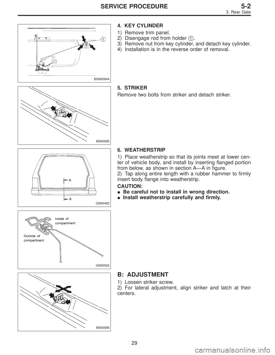
B5M0084A
4. KEY CYLINDER
1) Remove trim panel.
2) Disengage rod from holder�
1.
3) Remove nut from key cylinder, and detach key cylinder.
4) Installation is in the reverse order of removal.
B5M0085
5. STRIKER
Remove two bolts from striker and detach striker.
G5M0492
6. WEATHERSTRIP
1) Place weatherstrip so that its joints meet at lower cen-
ter of vehicle body, and install by inserting flanged portion
from below, as shown in section A—A in figure.
2) Tap along entire length with a rubber hammer to firmly
insert body flange into weatherstrip.
CAUTION:
�Be careful not to install in wrong direction.
�Install weatherstrip carefully and firmly.
G5M0552
B5M0086
B: ADJUSTMENT
1) Loosen striker screw.
2) For lateral adjustment, align striker and latch at their
centers.
29
5-2SERVICE PROCEDURE
3. Rear Gate
![SUBARU LEGACY 1995 Service Repair Manual 7) Installation is in the reverse order of removal.
Fitted length of heater hose over pipe:
25 — 30 mm (0.98 — 1.18 in)
8) Pour coolant. <Ref. to 2-5 [W1B0].>
B5M0025
3. Blower Motor Assembly
A: R](/manual-img/17/57432/w960_57432-852.png "SUBARU LEGACY 1995 Service Repair Manual 7) Installation is in the reverse order of removal.
Fitted length of heater hose over pipe:
25 — 30 mm (0.98 — 1.18 in)
8) Pour coolant. <Ref. to 2-5 [W1B0].>
B5M0025
3. Blower Motor Assembly
A: R")
![SUBARU LEGACY 1995 Service Repair Manual 7) Installation is in the reverse order of removal.
Fitted length of heater hose over pipe:
25 — 30 mm (0.98 — 1.18 in)
8) Pour coolant. <Ref. to 2-5 [W1B0].>
B5M0025
3. Blower Motor Assembly
A: R](/manual-img/17/57432/w960_57432-853.png "SUBARU LEGACY 1995 Service Repair Manual 7) Installation is in the reverse order of removal.
Fitted length of heater hose over pipe:
25 — 30 mm (0.98 — 1.18 in)
8) Pour coolant. <Ref. to 2-5 [W1B0].>
B5M0025
3. Blower Motor Assembly
A: R")
![SUBARU LEGACY 1995 Service Repair Manual B5M0310A
3. SUNROOF FRAME
1) Remove sunroof switch, center and rear room lamps.
2) Remove roof trim, rear quarter trim, pillar trim, etc.
<Ref. to 5-3 [W5A0].>
3) Remove glass lid assembly.
4) Remove](/manual-img/17/57432/w960_57432-972.png "SUBARU LEGACY 1995 Service Repair Manual B5M0310A
3. SUNROOF FRAME
1) Remove sunroof switch, center and rear room lamps.
2) Remove roof trim, rear quarter trim, pillar trim, etc.
<Ref. to 5-3 [W5A0].>
3) Remove glass lid assembly.
4) Remove")