Page 1009 of 2248
 Installation of glass
(1) Hold glass with rubber suction cups.
(2) Mount glass on body with matching pin aligned.
(3) Stick them fast by pressing all sides lightly.
G5M0496
10) Installation")
G5M0409
9) Installation of glass
(1) Hold glass with rubber suction cups.
(2) Mount glass on body with matching pin aligned.
(3) Stick them fast by pressing all sides lightly.
G5M0496
10) Installation of molding
(1) Remove adhesive overflowing from outside of
glass until it becomes level with outer height of glass.
Then, add adhesive to portions that need it, and clean
with alcohol or white gasoline.
(2) Install front side molding.
CAUTION:
Do not open and close door after moldings have been
installed. When opening and closing door for unavoid-
able reason, lower door glass and gently move door.
11) Water leakage test
Test for water leakage about one hour after installation.
CAUTION:
�Move vehicle very gently.
�Do not squirt strong hose stream on vehicle.
12) Spontaneous drying
After completing all operations, leave vehicle alone for 24
hours.
CAUTION:
When delivering vehicle to user, tell him that vehicle
should not be subjected to heavy shocks for at least
three days.
13) Install cowl panel and wiper arm.
6. Rear Window Glass
A: REMOVAL
1. 4 DOOR MODEL
1) Disconnect connector from rear defogger terminal.
2) Remove glass in the same manner as in windshield.
34
5-2SERVICE PROCEDURE
5. Windshield - 6. Rear Window Glass
Page 1010 of 2248
 Installation of glass
(1) Hold glass with rubber suction cups.
(2) Mount glass on body with matching pin aligned.
(3) Stick them fast by pressing all sides lightly.
G5M0496
10) Installation")
G5M0409
9) Installation of glass
(1) Hold glass with rubber suction cups.
(2) Mount glass on body with matching pin aligned.
(3) Stick them fast by pressing all sides lightly.
G5M0496
10) Installation of molding
(1) Remove adhesive overflowing from outside of
glass until it becomes level with outer height of glass.
Then, add adhesive to portions that need it, and clean
with alcohol or white gasoline.
(2) Install front side molding.
CAUTION:
Do not open and close door after moldings have been
installed. When opening and closing door for unavoid-
able reason, lower door glass and gently move door.
11) Water leakage test
Test for water leakage about one hour after installation.
CAUTION:
�Move vehicle very gently.
�Do not squirt strong hose stream on vehicle.
12) Spontaneous drying
After completing all operations, leave vehicle alone for 24
hours.
CAUTION:
When delivering vehicle to user, tell him that vehicle
should not be subjected to heavy shocks for at least
three days.
13) Install cowl panel and wiper arm.
6. Rear Window Glass
A: REMOVAL
1. 4 DOOR MODEL
1) Disconnect connector from rear defogger terminal.
2) Remove glass in the same manner as in windshield.
34
5-2SERVICE PROCEDURE
5. Windshield - 6. Rear Window Glass
Page 1012 of 2248
2. WAGON MODEL
B5M0090A
1) Install rear gate trim.
2) Install glass in the same manner as in windshield.
3) About one hour after installation, test for water leakage.
Leave vehicle for 24 hours before using it.
4) Connect rear defogger connections.
5) Install high-mount stop light and rear wiper.
36
5-2SERVICE PROCEDURE
6. Rear Window Glass
Page 1097 of 2248
Front wiper
motorInput 12 V—54 W or less
Rear wiper motor Input 12 V—42 W or less
Front washer
motorPump type Centrifugal
Input 12 V—36 W or less
Rear washer
motorPump type Centrifugal
Input 12 V—36 W or less
Horn12 V—350 Hz
Cigarette lighter Input 12 V—120 W
Rear window
defoggerInput 12 V—160 W
Indicator light 12 V—50 mA
3
6-2SPECIFICATIONS
1. Body Electrical
Page 1291 of 2248
B: ELECTRICAL WIRING HARNESS AND
GROUND POINT
B6M0267A
�1Front wiring harness
�
2Engine wiring harness
�
3Room light cord
�
4Bulkhead wiring harness
�
5Instrument panel wiring harness
�
6Front door cord RH
�
7Rear door cord RH
�
8Rear wiring harness
�
9Trunk lid cord (Sedan)�
10Rear defogger ground cord (Sedan)
�
11Fuel tank cord
�
12Rear door cord LH
�
13Front door cord LH
�
14Sunroof cord
�
15Floor wiring harness
�
16Transmission cord
�
17Rear gate cord (Wagon)
�
18Rear oxygen sensor cord
85
2-7ON-BOARD DIAGNOSTICS II SYSTEM
6. Wiring Diagram and Wiring Harness
Page 1308 of 2248
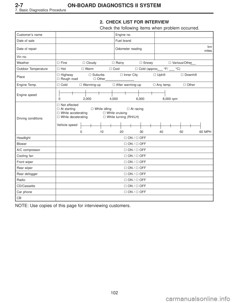
2. CHECK LIST FOR INTERVIEW
Check the following items when problem occurred.
Customer’s name Engine no.
Date of sale Fuel brand
Date of repair Odometer readingkm
miles
Vin no.
Weather�Fine�Cloudy�Rainy�Snowy�Various/Other
Outdoor Temperature�Hot�Warm�Cool�Cold (approx.°F/°C)
Place�Highway�Suburbs�Inner City�Uphill�Downhill
�Rough road�Other
Engine Temp.�Cold�Warming-up�After warming-up�Any temp.�Other
Engine speed
0 2,000 4,000 6,000 8,000 rpm
Driving conditions�Not affected
�At starting�While idling�At racing
�While accelerating�While cruising
�While decelerating�While turning (RH/LH)
Vehicle speed
0 10203040 5060MPH
Headlight�ON /�OFF
Blower�ON /�OFF
A/C compressor�ON /�OFF
Cooling fan�ON /�OFF
Front wiper�ON /�OFF
Rear wiper�ON /�OFF
Rear defogger�ON /�OFF
Radio�ON /�OFF
CD/Cassette�ON /�OFF
Car phone�ON /�OFF
CB
NOTE: Use copies of this page for interviewing customers.
102
2-7ON-BOARD DIAGNOSTICS II SYSTEM
7. Basic Diagnostics Procedure
Page 1893 of 2248
G6M0205
11) Each connector number shown in the wiring diagram
corresponds to that in the wiring harness. The location of
each connector in the actual vehicle is determined by read-
ing the first character of the connector (for example, a“F”
for F8,“i”for i16, etc.) and the type of wiring harness.
The first character of each connector number refers to the
area or system of the vehicle, as indicated in table below.
Symbol Wiring harness and Cord
F Front wiring harness
B Bulkhead wiring harness
E Engine wiring harness
T Transmission cord
D Door cord LH & RH, Rear gate cord
I Instrument panel wiring harness
RRear wiring harness, Rear defogger cord
Room light cord,
Fuel tank cord,
Sunroof cord,
Trunk lid cord
P Floor wiring harness
7
6-3WIRING DIAGRAM
1. General Description
Page 1906 of 2248

MB-2 Power window circuit breaker
MB-3Engine control module
Fuel pump relay
Main relay
OBD-II service connector
MB-4 A/C relay holder
MB-5 Headlight alarm")
No. Load
MB-1 Fuse holder (Rear power supply)
MB-2 Power window circuit breaker
MB-3Engine control module
Fuel pump relay
Main relay
OBD-II service connector
MB-4 A/C relay holder
MB-5 Headlight alarm relay (with security)
MB-6 Headlight LH
MB-7Combination meter
Daytime running light control module
Diode (Lighting)
Diode (Security)
Lighting switch
Luggage room light
Room light
Step light
Trunk room light
MB-8Combination meter
Front fog light switch
Headlight RH
MB-9Door lock timer
Headlight alarm relay
Interrupt relay
Radio
Security control module
Security indicator light
Spot light
MB-10 A/C relay holder
SBF-6Hydraulic unit (A.B.S.)
T.C.S. motor relay
SBF-7 T.C.S. valve relay
ALT-1Combination meter
Daytime running light control module
IG Headlight alarm relay
STCruise control module
Engine control module
Inhibitor switch (AT)
Interrupt relay
Starter interlock relay (MT)
FB-1Front washer motor
Rear washer motor
FB-2 Diode (A/C)
FB-3Sub fan motor
Sub fan relay-2
FB-4Engine control module
Fuel pump relay
Transmission control module
FB-5 Hydraulic unit (A.B.S.)
FB-6Front clearance light LH
Front clearance light RH
Side marker light LH
Side marker light RHNo. Load
FB-7 Door lock timer
FB-9 Hazard switch
FB-10AT shift lock control module
Key warning switch
Power antenna
FB-11 Radio
FB-12 Cigarette lighter
FB-13Remote control rearview mirror switch
Security control module
Vanity mirror illumination light
FB-14AT shift lock control module
Combination switch
Front wiper motor
Rear wiper motor
Rear wiper relay
FB-15A.B.S./T.C.S. control module
Transmission control module
FB-16Rear defogger
Rear defogger condenser
Rear defogger switch
FB-17 Rear defogger switch
FB-18AT shift lock control module
Back-up light switch (MT)
Inhibitor switch (AT)
FB-19 Hazard switch
FB-20A/C switch
Combination meter
Mode control panel
T.C.S. off switch
FB-21 Combination meter (Airbag)
FB-22Blower motor relay
Check connector
Daytime running light control module
Daytime running light relay
FRESH/RECIRC actuator
Hi-beam relay
Power window and sunroof relay
Seat belt timer
FB-23 Airbag control module
FB-24 Airbag control module
FB-25 Lighting switch
FB-26 Parking switch
FB-27 Parking switch
FB-28 Illumination light
FB-29 Illumination light
FB-30Pedal stroke sensor
Stop light switch
Stop & brake switch
FB-31 Horn relay
FB-32 Blower motor relay
FB-33 Parking switch
20
6-3WIRING DIAGRAM
6. Wiring Diagram
 Install rear gate trim.
2) Install glass in the same manner as in windshield.
3) About one hour after installation, test for water leakage.
Leave vehicle for 24 hours before")


 Each connector number shown in the wiring diagram
corresponds to that in the wiring harness. The location of
each connector in the actual vehicle is determined by read-
ing the first chara")