Page 116 of 2248
 O")
1. Engine Lubrication System
Before troubleshooting, make sure that the engine oil level
is correct and no oil leakage exists.
Trouble Possible cause Corrective action
1. Warning light remains
on.1) Oil pressure switch
failureCracked diaphragm or oil leakage within switch Replace.
Broken spring or seized contacts Replace.
2) Low oil pressureClogged oil filter Replace.
Malfunction of oil by-pass valve of oil filter Clean or replace.
Malfunction of oil relief valve of oil pump Clean or replace.
Clogged oil passage Clean.
Excessive tip clearance and side clearance of oil
pump rotor and gearReplace.
Clogged oil strainer or broken pipe Clean or replace.
3) No oil pressureInsufficient engine oil Replenish.
Broken pipe of oil strainer Replace.
Stuck oil pump rotor Replace.
2. Warning light does not
go on.1) Burn-out bulb Replace.
2) Poor contact of switch contact points Replace.
3) Disconnection of wiring Repair.
3. Warning light flickers
momentarily.1) Poor contact at terminals Repair.
2) Defective wiring harness Repair.
3) Low oil pressureCheck for the same pos-
sible causes as listed in
1.—2)
16
2-4DIAGNOSTICS
1. Engine Lubrication System
Page 139 of 2248

CONDITION:
�Engine coolant temperature is above 95°C (203°F).
TROUBLE SYMPTOM:
�Radiator main fan does not operate under the above
condition.
1. Check fuse and power")
A: OPERATION (WITHOUT A/C MODEL)
CONDITION:
�Engine coolant temperature is above 95°C (203°F).
TROUBLE SYMPTOM:
�Radiator main fan does not operate under the above
condition.
1. Check fuse and power supply.
OK
�Not OK
Melted fuse,repair the shorted part of the circuit
,replace fuse.
2. Check harness connector between fuse and
relay box, and A/C relay holder.
OK
�Not OK
Repair or replace wiring harness.
3. Check A/C relay holder.
OK
�Not OK
Repair or replace A/C relay holder.
4. Check harness connector between A/C relay
holder and main fan motor.
OK
�Not OK
Repair or replace wiring harness.
5. Check ground circuit of main fan motor.
OK
�Not OK
Repair or replace wiring harness.
6. Check main fan motor.
OK
�Not OK
Replace main fan motor.
Refer to 2-7 On-Board Diagnostics II System.
B2M0427A
1. CHECK FUSE AND POWER SUPPLY.
1) Check fuse No. 13.
2) Turn ignition switch to ACC.
3) Measure voltage between fuse and relay box, and body.
Connector & terminal / Specified voltage:
(F40) No. 3—Body / 10 V, or more
�
�
�
�
�
�
21
2-5DIAGNOSTICS
2. Radiator Main Fan
Page 141 of 2248
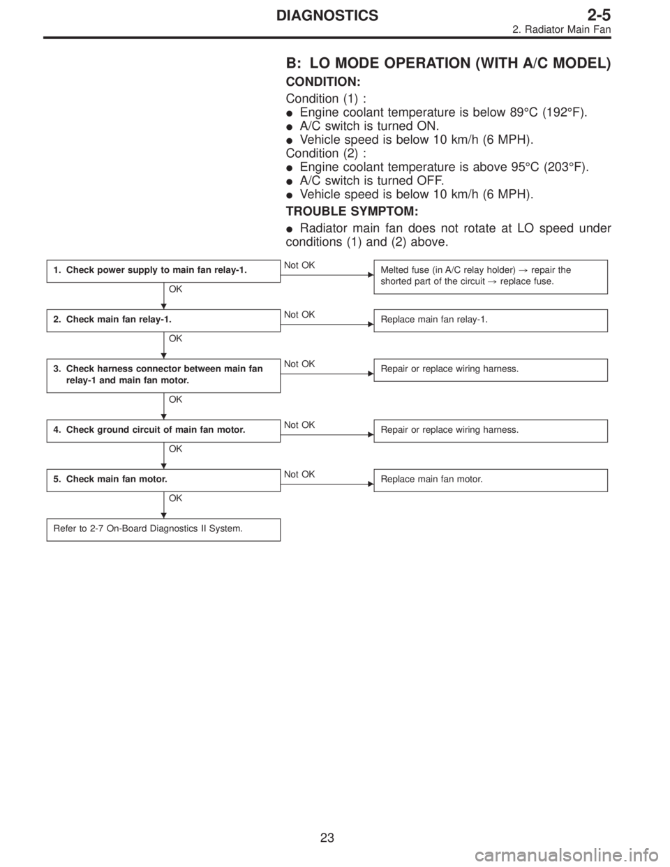
B: LO MODE OPERATION (WITH A/C MODEL)
CONDITION:
Condition (1) :
�Engine coolant temperature is below 89°C (192°F).
�A/C switch is turned ON.
�Vehicle speed is below 10 km/h (6 MPH).
Condition (2) :
�Engine coolant temperature is above 95°C (203°F).
�A/C switch is turned OFF.
�Vehicle speed is below 10 km/h (6 MPH).
TROUBLE SYMPTOM:
�Radiator main fan does not rotate at LO speed under
conditions (1) and (2) above.
1. Check power supply to main fan relay-1.
OK
�Not OK
Melted fuse (in A/C relay holder),repair the
shorted part of the circuit,replace fuse.
2. Check main fan relay-1.
OK
�Not OK
Replace main fan relay-1.
3. Check harness connector between main fan
relay-1 and main fan motor.
OK
�Not OK
Repair or replace wiring harness.
4. Check ground circuit of main fan motor.
OK
�Not OK
Repair or replace wiring harness.
5. Check main fan motor.
OK
�Not OK
Replace main fan motor.
Refer to 2-7 On-Board Diagnostics II System.
�
�
�
�
�
23
2-5DIAGNOSTICS
2. Radiator Main Fan
Page 144 of 2248

CONDITION:
Condition (1) :
�Engine coolant temperature is below 89°C (192°F).
�A/C switch is turned ON.
�Vehicle speed is over 20 km/h (12 MPH).
Condition (2) :")
C: HI MODE OPERATION (WITH A/C MODEL)
CONDITION:
Condition (1) :
�Engine coolant temperature is below 89°C (192°F).
�A/C switch is turned ON.
�Vehicle speed is over 20 km/h (12 MPH).
Condition (2) :
�Engine coolant temperature is above 95°C (203°F).
�A/C switch is turned OFF.
�Vehicle speed is over 20 km/h (12 MPH).
Condition (3) :
�Engine coolant temperature is above 95°C (203°F).
�A/C switch is turned ON.
TROUBLE SYMPTOM:
�Radiator main fan does not rotate at HI speed under
conditions (1), (2) and (3) above.
1. Check operation of main fan motor LO mode.
OK
�Not OK
Check LO mode operation.
2. Check power supply to main fan relay-2.
OK
�Not OK
Melted fuse (in A/C relay holder),repair the
shorted part of the circuit,replace fuse.
3. Check main fan relay-2.
OK
�Not OK
Replace main fan relay-2.
4. Check harness connector between main fan
relay-2 and main fan motor.
OK
�Not OK
Repair or replace wiring harness.
5. Check ground circuit of main fan motor.
OK
�Not OK
Repair or replace wiring harness.
6. Check main fan motor.
OK
�Not OK
Replace main fan motor.
Refer to 2-7 On-Board Diagnostics II System.
�
�
�
�
�
�
26
2-5DIAGNOSTICS
2. Radiator Main Fan
Page 148 of 2248
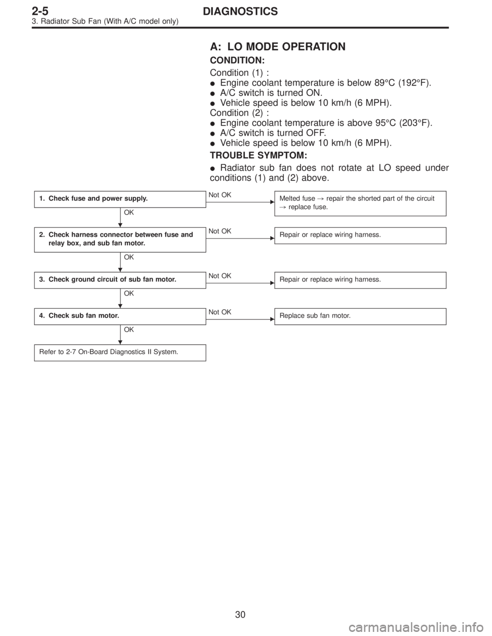
A: LO MODE OPERATION
CONDITION:
Condition (1) :
�Engine coolant temperature is below 89°C (192°F).
�A/C switch is turned ON.
�Vehicle speed is below 10 km/h (6 MPH).
Condition (2) :
�Engine coolant temperature is above 95°C (203°F).
�A/C switch is turned OFF.
�Vehicle speed is below 10 km/h (6 MPH).
TROUBLE SYMPTOM:
�Radiator sub fan does not rotate at LO speed under
conditions (1) and (2) above.
1. Check fuse and power supply.
OK
�Not OK
Melted fuse,repair the shorted part of the circuit
,replace fuse.
2. Check harness connector between fuse and
relay box, and sub fan motor.
OK
�Not OK
Repair or replace wiring harness.
3. Check ground circuit of sub fan motor.
OK
�Not OK
Repair or replace wiring harness.
4. Check sub fan motor.
OK
�Not OK
Replace sub fan motor.
Refer to 2-7 On-Board Diagnostics II System.
�
�
�
�
30
2-5DIAGNOSTICS
3. Radiator Sub Fan (With A/C model only)
Page 150 of 2248
 :
�Engine coolant temperature is below 89°C (192°F).
�A/C switch is turned ON.
�Vehicle speed is over 20 km/h (12 MPH).
Condition (2) :
�Engine coolant")
B: HI MODE OPERATION
CONDITION:
Condition (1) :
�Engine coolant temperature is below 89°C (192°F).
�A/C switch is turned ON.
�Vehicle speed is over 20 km/h (12 MPH).
Condition (2) :
�Engine coolant temperature is above 95°C (203°F).
�A/C switch is turned OFF.
�Vehicle speed is over 20 km/h (12 MPH).
Condition (3) :
�Engine coolant temperature is above 95°C (203°F).
�A/C switch is turned ON.
TROUBLE SYMPTOM:
�Radiator sub fan does not rotate at HI speed under con-
ditions (1), (2) and (3) above.
1. Check operation of sub fan motor LO mode.
OK
�Not OK
Check LO mode operation.
2. Check power supply to sub fan relay-2.
OK
�Not OK
Melted fuse (in A/C relay holder),repair the
shorted part of the circuit,replace fuse.
3. Check sub fan relay-2.
OK
�Not OK
Replace sub fan relay-2.
4. Check harness connector between sub fan
relay-2 and sub fan motor.
OK
�Not OK
Repair or replace wiring harness.
5. Check ground circuit of sub fan motor.
OK
�Not OK
Repair or replace wiring harness.
6. Check sub fan motor.
OK
�Not OK
Replace sub fan motor.
Refer to 2-7 On-Board Diagnostics II System.
�
�
�
�
�
�
32
2-5DIAGNOSTICS
3. Radiator Sub Fan (With A/C model only)
Page 625 of 2248
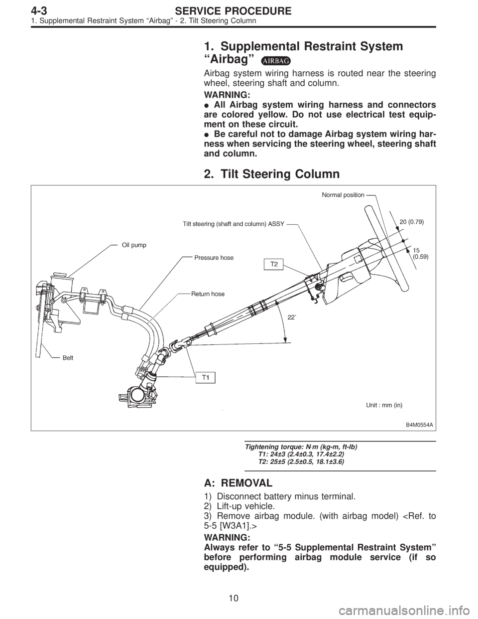
1. Supplemental Restraint System
“Airbag”
Airbag system wiring harness is routed near the steering
wheel, steering shaft and column.
WARNING:
�All Airbag system wiring harness and connectors
are colored yellow. Do not use electrical test equip-
ment on these circuit.
�Be careful not to damage Airbag system wiring har-
ness when servicing the steering wheel, steering shaft
and column.
2. Tilt Steering Column
B4M0554A
Tightening torque: N⋅m (kg-m, ft-lb)
T1: 24±3 (2.4±0.3, 17.4±2.2)
T2: 25±5 (2.5±0.5, 18.1±3.6)
A: REMOVAL
1) Disconnect battery minus terminal.
2) Lift-up vehicle.
3) Remove airbag module. (with airbag model)
5-5 [W3A1].>
WARNING:
Always refer to“5-5 Supplemental Restraint System”
before performing airbag module service (if so
equipped).
10
4-3SERVICE PROCEDURE
1. Supplemental Restraint System“Airbag”- 2. Tilt Steering Column
Page 626 of 2248
1. Supplemental Restraint System
“Airbag”
Airbag system wiring harness is routed near the steering
wheel, steering shaft and column.
WARNING:
�All Airbag system wiring harness and connectors
are colored yellow. Do not use electrical test equip-
ment on these circuit.
�Be careful not to damage Airbag system wiring har-
ness when servicing the steering wheel, steering shaft
and column.
2. Tilt Steering Column
B4M0554A
Tightening torque: N⋅m (kg-m, ft-lb)
T1: 24±3 (2.4±0.3, 17.4±2.2)
T2: 25±5 (2.5±0.5, 18.1±3.6)
A: REMOVAL
1) Disconnect battery minus terminal.
2) Lift-up vehicle.
3) Remove airbag module. (with airbag model)
5-5 [W3A1].>
WARNING:
Always refer to“5-5 Supplemental Restraint System”
before performing airbag module service (if so
equipped).
10
4-3SERVICE PROCEDURE
1. Supplemental Restraint System“Airbag”- 2. Tilt Steering Column