Page 2 of 2248
B2M0060
7) Separate front catalytic converter from front exhaust
pipe and center exhaust pipe.
B2M0060
B: INSTALLATION
CAUTION:
Replace gaskets with new ones.
1) Install front catalytic converter to front exhaust pipe and
center exhaust pipe.
Tightening torque:
30±5 N⋅m (3.1±0.5 kg-m, 22.4±3.6 ft-lb)
B2M0313
2) Install front exhaust pipe and center exhaust pipe.
And temporarily tighten bolt which installs center exhaust
pipe to hanger bracket.
B2M0054
3) Tighten bolts which hold front exhaust pipe onto cylin-
der heads.
Tightening torque:
30±5 N⋅m (3.1±0.5 kg-m, 22.4±3.6 ft-lb)
B2M0055
4) Install center exhaust pipe to rear exhaust pipe.
Tightening torque:
18±5 N⋅m (1.8±0.5 kg-m, 13.0±3.6 ft-lb)
3
2-1SERVICE PROCEDURE
1. Front Catalytic Converter
Page 26 of 2248
2. Cylinder Head and Camshaft
B2M0103A
�1Rocker cover (RH)
�
2Rocker cover gasket
�
3Camshaft support (RH)
�
4O-ring
�
5Camshaft (RH)
�
6Intake valve guide
�
7Exhaust valve guide
�
8Oil seal
�
9Cylinder head (RH)
�
10Cylinder head gasket
�
11Cylinder head (LH)
�
12Plug
�
13Camshaft (LH)
�
14O-ring
�
15Camshaft support (LH)�
16Oil seal
�
17Oil filler cap
�
18Gasket
�
19Oil filler pipe
�
20O-ring
�
21Rocker cover gasket
�
22Rocker cover (LH)
Tightening torque: N⋅m (kg-m, ft-lb)
T1: Refer to [W6E1].
T2: 5±1 (0.5±0.1, 3.6±0.7)
T3: 10 (1.0, 7)
T4: 16 (1.6, 12)
7
2-3COMPONENT PARTS
2. Cylinder Head and Camshaft
Page 60 of 2248
2. CYLINDER HEAD
B2M0119A
1) Remove timing belt, camshaft sprocket and related
parts.
2) Remove oil level gauge guide attaching bolt (left hand
only) and oil level gauge guide.
B2M0120A
3) Remove cylinder head bolts in numerical sequence
shown in Figure.
CAUTION:
Leave bolts�
1and�3engaged by three or four threads
to prevent cylinder head from falling.
4) While tapping cylinder head with a plastic hammer,
separate it from cylinder block.
Remove bolts�
1and�3to remove cylinder head.
5) Remove cylinder head gasket.
CAUTION:
Do not scratch the mating surface of cylinder head and
cylinder block.
6) Similarly, remove right side cylinder head.
39
2-3SERVICE PROCEDURE
6. Cylinder Head
Page 62 of 2248

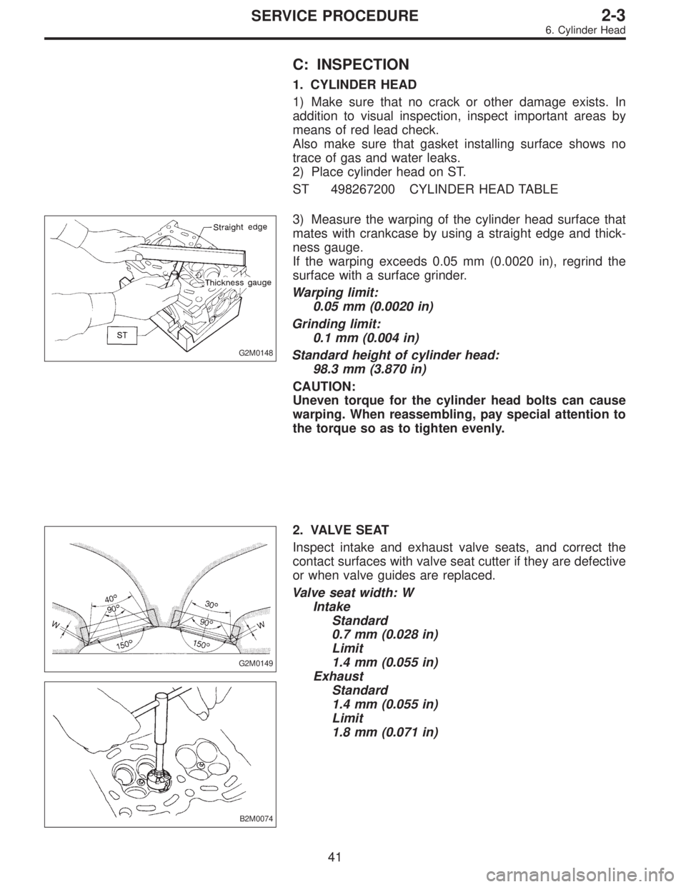
C: INSPECTION
1. CYLINDER HEAD
1) Make sure that no crack or other damage exists. In
addition to visual inspection, inspect important areas by
means of red lead check.
Also make sure that gasket installing surface shows no
trace of gas and water leaks.
2) Place cylinder head on ST.
ST 498267200 CYLINDER HEAD TABLE
G2M0148
3) Measure the warping of the cylinder head surface that
mates with crankcase by using a straight edge and thick-
ness gauge.
If the warping exceeds 0.05 mm (0.0020 in), regrind the
surface with a surface grinder.
Warping limit:
0.05 mm (0.0020 in)
Grinding limit:
0.1 mm (0.004 in)
Standard height of cylinder head:
98.3 mm (3.870 in)
CAUTION:
Uneven torque for the cylinder head bolts can cause
warping. When reassembling, pay special attention to
the torque so as to tighten evenly.
G2M0149
B2M0074
2. VALVE SEAT
Inspect intake and exhaust valve seats, and correct the
contact surfaces with valve seat cutter if they are defective
or when valve guides are replaced.
Valve seat width: W
Intake
Standard
0.7 mm (0.028 in)
Limit
1.4 mm (0.055 in)
Exhaust
Standard
1.4 mm (0.055 in)
Limit
1.8 mm (0.071 in)
41
2-3SERVICE PROCEDURE
6. Cylinder Head
Page 69 of 2248
E: INSTALLATION
1. CYLINDER HEAD
B2M0119B
1) Install cylinder head and gaskets on cylinder block.
CAUTION:
Use new cylinder head gaskets.
B2M0120B
2) Tighten cylinder head bolts.
(1) Apply a coat of engine oil to washers and bolt
threads.
(2) Tighten all bolts to 29 N⋅m (3.0 kg-m, 22 ft-lb) in
numerical sequence.
Then tighten all bolts to 69 N⋅m (7.0 kg-m, 51 ft-lb) in
numerical sequence.
(3) Back off all bolts by 180°first; back them off by 180°
again.
(4) Tighten bolts�
1and�2to 34 N⋅m (3.5 kg-m, 25 ft-
lb).
(5) Tighten bolts�
3,�4,�5and�6to 15 N⋅m (1.5 kg-m,
11 ft-lb).
(6) Tighten all bolts by 80 to 90°in numerical
sequence.
CAUTION:
Do not tighten bolts more than 90°.
48
2-3SERVICE PROCEDURE
6. Cylinder Head
Page 95 of 2248
B2M0390A
(2) Apply fluid packing to matching surface of oil pump.
Fluid packing:
THREE BOND 1215 or equivalent
(3) Install oil pump on cylinder block. Be careful not to
damage oil seal during installation.
CAUTION:
�Do not forget to install O-ring and seal when install-
ing oil pump.
�Align flat surface of oil pump’s inner rotor with
crankshaft before installation.
G2M0628
9) Install engine coolant pump and gasket.
CAUTION:
�Be sure to use a new gasket.
�When installing engine coolant pump, tighten bolts
in two stages in numerical sequence as shown in Fig-
ure.
10) Install engine coolant pipe.
11) Install oil filter.
2. RELATED PARTS
1) Install cylinder head and intake manifold.
2) Install timing belt, camshaft sprocket and related parts.
74
2-3SERVICE PROCEDURE
7. Cylinder Block
Page 97 of 2248

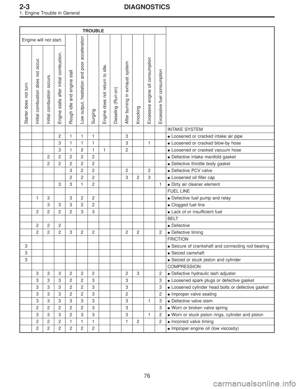
TROUBLE
Engine will not start.
Rough idle and engine stall
Low output, hesitation and poor acceleration
Surging
Engine does not return to idle.
Dieseling (Run-on)
After burning in exhaust system
Knocking
Excessive engine oil consumption
Excessive fuel consumption Starter does not turn.
Initial combustion does not occur.
Initial combustion occurs.
Engine stalls after initial combustion.
INTAKE SYSTEM
2111 3�Loosened or cracked intake air pipe
3111 3 1�Loosened or cracked blow-by hose
31211 2�Loosened or cracked vacuum hose
22222�Defective intake manifold gasket
22222�Defective throttle body gasket
322 2 2�Defective PCV valve
222 323�Loosened oil filler cap
3312 1�Dirty air cleaner element
FUEL LINE
13 322�Defective fuel pump and relay
33322�Clogged fuel line
222233�Lack of or insufficient fuel
BELT
222�Defective
222322 22 2�Defective timing
FRICTION
3�Seizure of crankshaft and connecting rod bearing
3�Seized camshaft
3�Seized or stuck piston and cylinder
COMPRESSION
333222 23 2�Defective hydraulic lash adjuster
333223 3 3�Loosened spark plugs or defective gasket
333223 3 3�Loosened cylinder head bolts or defective gasket
333223 2 2�Improper valve seating
333333 3 13�Defective valve stem
222223 3 3�Worn or broken valve spring
333233 3 12�Worn or stuck piston rings, cylinder and piston
222111 12 2�Incorrect valve timing
222222�Improper engine oil (low viscosity)
76
2-3DIAGNOSTICS
1. Engine Trouble in General
Page 137 of 2248

1. Engine Cooling System
Trouble Possible cause Corrective action
Over-heatinga. Insufficient engine coolantReplenish engine coolant, inspect for leakage, and
repair.
b. Loose timing belt Repair or replace timing belt tensioner.
c. Oil on drive belt Replace.
d. Malfunction of thermostat Replace.
e. Malfunction of engine coolant pump Replace.
f. Clogged engine coolant passage Clean.
g. Improper ignition timingInspect and repair ignition control system.
h. Clogged or leaking radiator Clean or repair, or replace.
i. Improper engine oil in engine coolant Replace engine coolant.
j. Air/fuel mixture ratio too leanInspect and repair fuel injection system.
k. Excessive back pressure in exhaust system Clean or replace.
l. Insufficient clearance between piston and cylinder Adjust or replace.
m. Slipping clutch Repair or replace.
n. Dragging brake Adjust.
o. Improper transmission oil Replace.
p. Defective thermostat Replace.
q. Malfunction of electric fanInspect radiator fan relay, engine coolant temperature
sensor or radiator motor and replace there.
Over-coolinga. Atmospheric temperature extremely low Partly cover radiator front area.
b. Defective thermostat Replace.
Engine coolant
leaks.a. Loosened or damaged connecting units on hoses Repair or replace.
b. Leakage from engine coolant pump Replace.
c. Leakage from engine coolant pipe Repair or replace.
d. Leakage around cylinder head gasket Retighten cylinder head bolts or replace gasket.
e. Damaged or cracked cylinder head and crankcase Repair or replace.
f. Damaged or cracked thermostat case Repair or replace.
g. Leakage from radiator Repair or replace.
Noisea. Defective drive belt Replace.
b. Defective radiator fan Replace.
c. Defective engine coolant pump bearing Replace engine coolant pump.
d. Defective engine coolant pump mechanical seal Replace engine coolant pump.
19
2-5DIAGNOSTICS
1. Engine Cooling System