Page 764 of 2248
G4M0425
3) Use care when placing brake booster on the floor.
CAUTION:
If external force is applied from above when brake
booster is placed in this position, the resin portion as
indicated by“P”, may be damaged.
G4M0424
4) Do not change the push rod length. If it has been
changed, reset the projected length“L”to the standard
length.
Standard:
L = 10 mm (0.39 in)
48
4-4SERVICE PROCEDURE
6. Brake Booster
Page 1234 of 2248
 Prepare a general scan tool (OBD-II general scan tool)
required by SAE J1978.
2) Open the cover and connect the OBD-II ge")
OBD0006C
B: OBD-II GENERAL SCAN TOOL
1. HOW TO USE OBD-II GENERAL SCAN TOOL
1) Prepare a general scan tool (OBD-II general scan tool)
required by SAE J1978.
2) Open the cover and connect the OBD-II general scan
tool to the data link connector located in the lower portion
of the instrument panel (on the driver’s side), to the lower
cover.
3) Using the OBD-II general scan tool, call up diagnostic
trouble code(s) and freeze frame data.
OBD-II general scan tool functions consist of:
(1) MODE $01: Current powertrain diagnostic data
(2) MODE $02: Powertrain freeze frame data
(3) MODE $03: Emission-related powertrain diagnostic
trouble codes
(4) MODE $04: Clear/Reset emission-related diagnos-
tic information
(5) MODE $05: Oxygen sensor monitoring test results
Read out data according to repair procedures.
(For detailed operation procedures, refer to the OBD-II
General Scan Tool Operation Manual.)
NOTE:
For details concerning diagnostic trouble codes, refer to
the DIAGNOSTIC TROUBLE CODE (DTC) LIST [T11A0].
H2M1280
2. DATA LINK CONNECTOR (FOR OBD-II GENERAL
SCAN TOOL AND SUBARU SELECT MONITOR)
1) This connector is used both for OBD-II general scan
tools and Subaru Select Monitor.
2) Terminal No. 4 to No. 6 of data link connector is used
for Subaru Select Monitor signal.
CAUTION:
Do not connect scan tools other than OBD-II general
scan tools and Subaru Select Monitor, because the
circuit for Subaru Select Monitor may be damaged.
Terminal No. Contents Terminal No. Contents
1 Power supply 9 Blank
2 Blank10 K line of ISO 9141 CARB
3 Blank11 Blank
4 Subaru Select Monitor signal (ECM to Subaru Select monitor)* 12 Ground
5 Subaru Select Monitor signal (Subaru Select monitor to ECM)* 13 Ground
6 Subaru Select Monitor clock* 14 Blank
7 Blank15 Blank
8 Blank16 Blank
*: Circuit only for Subaru Select Monitor
28
2-7ON-BOARD DIAGNOSTICS II SYSTEM
3. Diagnosis System
Page 1237 of 2248
.
NOTE:
R")
�MODE $04
—Clear/Reset emission-related diagnostic information—
Refers to the mode used to clear or reset emission-related
diagnostic information (OBD-II trouble diagnostic informa-
tion).
NOTE:
Refer to OBD-II general scan tool manufacturer’s instruc-
tion manual to clear or reset emission-related diagnostic
information (MODE $04).
�MODE $05
—Oxygen sensor monitoring test results—
Refers to the mode using oxygen sensor output data while
the on-board diagnosis system is performing diagnosis on
the oxygen sensor.
A list of the support oxygen sensor output data and test ID
(identification) are shown in the following table.
Test ID DataUnit of measure
01 Rich to lean sensor threshold voltage (constant) V
02 Lean to rich sensor threshold voltage (constant) V
03 Low sensor voltage for switch time calculation (constant) V
04 High sensor voltage for switch time calculation (constant) V
05 Rich to lean sensor switch time (calculated) sec.
06 Lean to rich sensor switch time (calculated) sec.
07 Minimum sensor voltage for test cycle (calculated) V
08 Maximum sensor voltage for test cycle (calculated) V
NOTE:
Refer to OBD-II general scan tool manufacturer’s instruc-
tion manual to access oxygen sensor monitoring test
results (MODE $05).
31
2-7ON-BOARD DIAGNOSTICS II SYSTEM
3. Diagnosis System
Page 1462 of 2248
OBD0358
OBD0688A
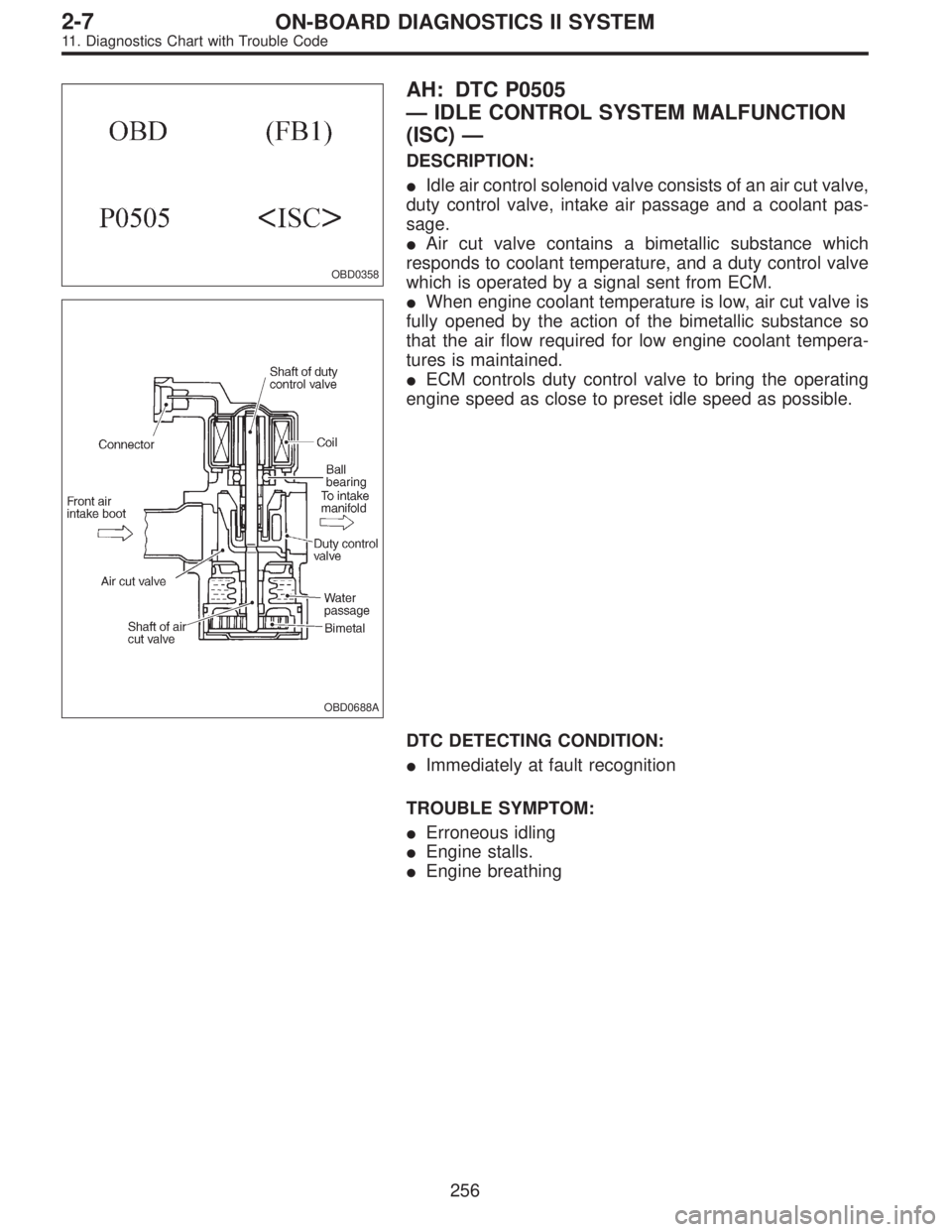
AH: DTC P0505
—IDLE CONTROL SYSTEM MALFUNCTION
(ISC)—
DESCRIPTION:
�Idle air control solenoid valve consists of an air cut valve,
duty control valve, intake air passage and a coolant pas-
sage.
�Air cut valve contains a bimetallic substance which
responds to coolant temperature, and a duty control valve
which is operated by a signal sent from ECM.
�When engine coolant temperature is low, air cut valve is
fully opened by the action of the bimetallic substance so
that the air flow required for low engine coolant tempera-
tures is maintained.
�ECM controls duty control valve to bring the operating
engine speed as close to preset idle speed as possible.
DTC DETECTING CONDITION:
�Immediately at fault recognition
TROUBLE SYMPTOM:
�Erroneous idling
�Engine stalls.
�Engine breathing
256
2-7ON-BOARD DIAGNOSTICS II SYSTEM
11. Diagnostics Chart with Trouble Code
Page 1809 of 2248
 and,
when it operates, acceleration can become slow*. T")
12. Phenomena Peculiar to the System
1. WHEN TRAVELING WITH EXTREMELY UNDER
INFLATED TIRES
The TCS is apt to operate (particularly when turning) and,
when it operates, acceleration can become slow*. This
state is not abnormal. Immediately restore the tires to nor-
mal by traveling after releasing the TCS with the TCS OFF
switch.
* Poor acceleration is sometimes caused by the engine
itself. Check whether or not the TCS operating indicator
light (green) comes on to determine that the failure is
caused by the TCS control.
2. WHEN THE T TIRES ARE FITTED
The TCS is apt to operate (particularly when turning) and,
when it operates, acceleration can become slow. This state
is not abnormal. Immediately restore the tires to normal by
traveling after releasing the TCS with the TCS OFF switch.
3. WHEN OPERATING THE TCS CONTINUOUSLY ON
A SLOPE IMPOSSIBLE TO CLIMB OR IN STACK
S TAT E
When operating the TCS for a long time, it can be auto-
matically turned off (the OFF indicator light will come on),
stopping braking. This state is not abnormal. It automati-
cally resets by stopping and leaving the vehicle.
4. WHEN HEAVY LOAD IS PLACED ON THE BRAKES
If service brakes are used too often when descending a
long slope, heavy load can be placed on the brakes. To
prevent this problem, the TCS is automatically turned off
(the OFF indicator light will come on). This state is not
abnormal. Stop the vehicle and leave it in the same way as
step 3, it automatically resets.
5. KICKBACK TO THE BRAKE PEDAL WHEN THE
ABS IS OPERATING
Compared with ABS of the AWD model system, pedal kick-
back with large amplitude of vibration and long cycle can
be felt. This is caused by the difference in system configu-
ration and, therefore, not abnormal. If you receive an
inquiry from your clients, fully explain this point.
128
4-4bBRAKES
12. Phenomena Peculiar to the System
Page 2239 of 2248

Connect the positive probe to the terminal to be tested, and
the negative probe to")
Diagnosis and checking procedure using instruments
USING A CIRCUIT TESTER
J3-1012
�Voltage check (range set to DC V)
Connect the positive probe to the terminal to be tested, and
the negative probe to body ground (or the ground terminal of
the ECM)
J3-830
�Checking the connection (range set toΩ)
Measure the resistance and check for open or shorted wire in
the harness or the connector.
NOTE:
This check must be carried out with both connectors discon-
nected.
(This avoids by-passing the connection through other circuits).
1) Check for open circuit (range:Ωx 1K)
Measure the resistance between the respective pins in both
connectors.
Specified resistance:
1MΩ, or more (No continuity) Open circuit
10Ω, or less (Continuity) O.K.
2) Check for correct insulation value (range:Ωx 1K)
Measure the resistance between the pins in both connectors,
as well as between the suspected pin and the body (body
short).
Specified resistance:
1MΩ, or more (No continuity) O.K.
10Ω, or less (Continuity) Short circuit
�Resistance measurement (range set toΩ)
Measuring the internal resistance of sensors, solenoid valves
etc. to check the operating condition of components.
NOTE:
�Select the appropriate range for measuring the internal
resistance, or the measurement will result in an incorrect read-
ing.
�Before changing the measurement range the gauge must be
reset to zero.
8
 Use care when placing brake booster on the floor.
CAUTION:
If external force is applied from above when brake
booster is placed in this position, the resin portion as
indicated by“P”, m")