Page 1176 of 2248
B3M0289
1) Disconnect connector from vehicle speed sensor 2.
2) Measure resistance between terminals of vehicle speed
sensor 2.
Terminals / Specified resistance:
No. 1—No. 2 / 350—450Ω
B3M0256
WARNING:
Be careful not to be caught up by the running wheels.
3) Set the vehicle on free roller, or lift-up the vehicle and
support with safety stands.
4) Drive the vehicle at speed greater than 20 km/h (12
MPH).
5) Measure voltage between terminals of vehicle speed
sensor 2.
Terminals / Specified voltage:
No. 1—No.2/5V,min. (AC range)
B3M0257
�Using an oscilloscope:
(1) Turn ignition switch to OFF.
(2) Set oscilloscope to vehicle speed sensor 2.
(3) Drive the vehicle at speed greater than 20 km/h (12
MPH).
(4) Measure signal voltage.
Specified voltage (V): 5 V, min.
B3M0254A
72
6-2DIAGNOSTICS
3. Combination Meter
Page 1264 of 2248
 After the display is gone, turn Subaru select monitor
switch and ignition switch to OFF.
NOTE:
When the ECM, battery terminals, etc. are disconnected
after memory is cleared, idling speed m")
G3M0151
6) After the display is gone, turn Subaru select monitor
switch and ignition switch to OFF.
NOTE:
When the ECM, battery terminals, etc. are disconnected
after memory is cleared, idling speed may increase. This is
not considered a problem because the ISC valve duty con-
trolled learning value has been cleared. To return the
engine to idling speed, idle for approximately 2 minutes
with air conditioner off.
2. OBD-II GENERAL SCAN TOOL
For clear memory procedures using the OBD-II general
scan tool, refer to the OBD-II General Scan Tool Instruction
Manual.
OBD0072A
E: INSPECTION MODE
1. PREPARATIONS FOR THE INSPECTION MODE
Raise the vehicle using a garage jack and place on safety
stands or drive the vehicle onto free rollers.
�FULL-TIME AWD MODELS
WARNING:
�Before raising the vehicle, ensure parking brakes
are applied.
�Do not use a pantograph jack in place of a safety
stand.
�Secure a rope or wire to the front and rear towing or
tie-down hooks to prevent the lateral runout of front
wheels.
�Do not abruptly depress/release clutch pedal or
accelerator pedal during works even when engine is
operating at low speeds since this may cause vehicle
to jump off free rollers.
�In order to prevent the vehicle from slipping due to
vibration, do not place any wooden blocks or similar
items between the safety stands and the vehicle.
58
2-7ON-BOARD DIAGNOSTICS II SYSTEM
3. Diagnosis System
Page 1480 of 2248
—
OBD0592A
DESCRIPTION:
�The inhibitor switch assures safety when starting the
engine. This switch is mounted on the right")
OBD0591
AN: DTC P0705
—TRANSMISSION RANGE SENSOR CIRCUIT
MALFUNCTION (RNG)—
OBD0592A
DESCRIPTION:
�The inhibitor switch assures safety when starting the
engine. This switch is mounted on the right side of the
transmission case, and is operated by the range selector
lever.
�When the selector lever is set to“P”or“N”, the electri-
cal circuit is connected in the inhibitor switch and the starter
circuit is energized for cracking the engine.
�When the selector lever is set to“R”,“D”,“3”,“2”,or“1”
range, the electrical circuit is disconnected in the inhibitor
switch. Hence engine cranking is disabled. In the“R”
range, the back-up light circuit is completed in the switch,
and the back-up lights come on.
DTC DETECTING CONDITION:
�Two consecutive trips with fault
TROUBLE SYMPTOM:
�Starter does not rotate when selector lever is in“P”or
“N”range.
�Starter rotates when selector lever is in“R”,“D”,“3”,“2”
or“1”range.
�Engine brake is not effected when selector lever is in“3”
range.
�Shift characteristics are erroneous.
274
2-7ON-BOARD DIAGNOSTICS II SYSTEM
11. Diagnostics Chart with Trouble Code
Page 1511 of 2248
 Lift-up or raise the vehicle and support with safety
stands.
CAUTION:
On AWD models, raise all wheels off ground.
4) Start and warm-up the engine and transmission.
5) Subaru select monitor")
OBD0615
3) Lift-up or raise the vehicle and support with safety
stands.
CAUTION:
On AWD models, raise all wheels off ground.
4) Start and warm-up the engine and transmission.
5) Subaru select monitor switch to ON.
6) Designate mode using function key.
Function mode for AT: F10
7) Move selector lever to“D”and drive the vehicle.
8) Read data on Subaru select monitor.
: Change gear position according to throttle
position and vehicle speed.
: Go to next.
: Go to step 4.
: Is there poor contact in TCM connector?
: Repair poor contact in TCM connector.
: Go to next.
: Is there any mechanical trouble in automatic
transmission?
: Repair or replace automatic transmission.
: Replace TCM with a new one.
4
CHECK SHIFT SOLENOID 1 CIRCUIT.
: Is there any trouble in shift solenoid 1 cir-
cuit?
: Repair or replace shift solenoid 1 circuit.
: Go to step 5.
5
CHECK SHIFT SOLENOID 2 CIRCUIT.
: Is there any trouble in shift solenoid 2 cir-
cuit?
: Repair or replace shift solenoid 2 circuit.
: Go to step 6.
305
2-7ON-BOARD DIAGNOSTICS II SYSTEM
11. Diagnostics Chart with Trouble Code
Page 1602 of 2248
 Connect connectors to TCM and transmission.
2) Lift-up or raise the vehicle and place safety stands.
CAUTION:
On AWD models, raise all wheels off floor.
3) P")
OBD0396A
3. CHECK INPUT SIGNAL FOR TCM.
1) Connect connectors to TCM and transmission.
2) Lift-up or raise the vehicle and place safety stands.
CAUTION:
On AWD models, raise all wheels off floor.
3) Push the TCS OFF switch to ON. (With TCS models)
4) Start the engine and set vehicle in 20 km/h (12 MPH)
condition.
5) Measure voltage between TCM connector terminals.
Connector & terminal / Specified voltage:
(B54) No. 12—No. 7 / AC 1 V, or more
NOTE:
The speed difference between front and rear wheels may
light either the ABS or the ABS/TCS warning light, but this
indicates no malfunctions. When AT control diagnosis is
finished, perform the ABS or the ABS/TCS memory clear-
ance procedure of self-diagnosis system.
OBD0145A
B3M0413
OBD0399
�Using Subaru select monitor:
(1) Connect connectors to TCM and transmission.
(2) Turn ignition switch to OFF.
(3) Connect the Subaru select monitor to data link con-
nector.
(4) Lift-up or raise the vehicle and place safety stands.
CAUTION:
On AWD models, raise all wheels off floor.
(5) Turn ignition switch to ON and Subaru select moni-
tor switch to ON.
(6) Push the TCS OFF switch to ON. (With TCS mod-
els)
(7) Start the engine and operate at constant speed.
(8) Read data on Subaru select monitor.
(9) Designate mode using function key.
Function mode: F02 or F03
SPECIFIED DATA:
F02: Compare speedometer with monitor indica-
tions.
F03: Compare speedometer with monitor indica-
tions.
�F02: Vehicle speed is indicated in“m/h”.
�F03: Vehicle speed is indicated in“km/h”.
NOTE:
The speed difference between front and rear wheels may
light either the ABS or the ABS/TCS warning light, but this
indicates no malfunctions. When AT control diagnosis is
finished, perform the ABS or the ABS/TCS memory clear-
ance procedure of self-diagnosis system.
47
3-2AUTOMATIC TRANSMISSION AND DIFFERENTIAL
7. Diagnostic Chart with Trouble Code
Page 1603 of 2248
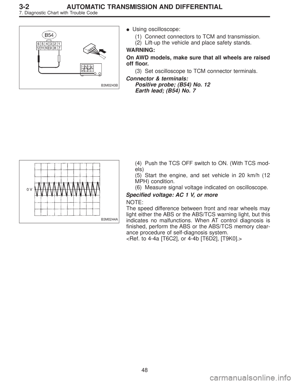
B3M0243B
�Using oscilloscope:
(1) Connect connectors to TCM and transmission.
(2) Lift-up the vehicle and place safety stands.
WARNING:
On AWD models, make sure that all wheels are raised
off floor.
(3) Set oscilloscope to TCM connector terminals.
Connector & terminals:
Positive probe; (B54) No. 12
Earth lead; (B54) No. 7
B3M0244A
(4) Push the TCS OFF switch to ON. (With TCS mod-
els)
(5) Start the engine, and set vehicle in 20 km/h (12
MPH) condition.
(6) Measure signal voltage indicated on oscilloscope.
Specified voltage: AC 1 V, or more
NOTE:
The speed difference between front and rear wheels may
light either the ABS or the ABS/TCS warning light, but this
indicates no malfunctions. When AT control diagnosis is
finished, perform the ABS or the ABS/TCS memory clear-
ance procedure of self-diagnosis system.
48
3-2AUTOMATIC TRANSMISSION AND DIFFERENTIAL
7. Diagnostic Chart with Trouble Code
Page 1606 of 2248
 Install combination meter.
2) Connect connector to TCM.
3) Lift-up the vehicle and place safety stand.
CAUTION:
On AWD models, raise all wheels off floor.
4")
B3M0289
3. CHECK VEHICLE SPEED SENSOR 2.
1) Install combination meter.
2) Connect connector to TCM.
3) Lift-up the vehicle and place safety stand.
CAUTION:
On AWD models, raise all wheels off floor.
4) Disconnect connector from vehicle speed sensor 2.
5) Measure resistance between terminals of vehicle speed
sensor 2.
Terminals / Specified resistance:
(B17) No. 1—No. 2 / 350—450Ω
No. 1—Body/1MΩ, or more
No. 2—Body/1MΩ, or more
B3M0256
6) Push the TCS OFF switch to ON. (With TCS models)
7) Start the engine and set vehicle in 20 km/h (12 MPH)
condition.
8) Measure output signal of vehicle speed sensor 2.
WARNING:
Be careful not to be caught up by the running wheels.
9) Using a voltage meter; measure voltage between termi-
nals of vehicle speed sensor 2.
Terminals / Specified voltage:
(B17) No. 1—No. 2 / AC 2 V, or more
NOTE:
The speed difference between front and rear wheels may
light either the ABS or the ABS/TCS warning light, but this
indicates no malfunctions. When AT control diagnosis is
finished, perform the ABS or the ABS/TCS memory clear-
ance procedure of self-diagnosis system.
51
3-2AUTOMATIC TRANSMISSION AND DIFFERENTIAL
7. Diagnostic Chart with Trouble Code
Page 1607 of 2248
 Install combination meter.
(2) Connect connector to TCM.
(3) Lift-up the vehicle and place safety stand.
WARNING:
On AWD models, make sure that all wheels are raised
o")
B3M0257
�Using oscilloscope:
(1) Install combination meter.
(2) Connect connector to TCM.
(3) Lift-up the vehicle and place safety stand.
WARNING:
On AWD models, make sure that all wheels are raised
off floor.
(4) Set oscilloscope to vehicle speed sensor 2.
Connector & terminal / No. 1—No. 2
B3M0254A
(5) Push the TCS OFF switch to ON. (With TCS mod-
els)
(6) Start the engine, and drive the wheels slowly.
(7) Measure signal voltage indicated on oscilloscope.
Specified voltage: AC 2 V, or more
NOTE:
The speed difference between front and rear wheels may
light either the ABS or the ABS/TCS warning light, but this
indicates no malfunctions. When AT control diagnosis is
finished, perform the ABS or the ABS/TCS memory clear-
ance procedure of self-diagnosis system.
B3M0369A
4. CHECK INPUT SIGNAL FOR TCM.
1) Connect connector to vehicle speed sensor 2.
2) Lift-up the vehicle or set the vehicle on free roller.
CAUTION:
On AWD models, raise all wheels off floor.
3) Push the TCS OFF switch to ON. (With TCS models)
4) Start the engine, and drive the wheels slowly.
5) Measure voltage between TCM and body.
Connector & terminal / Specified voltage:
(B56) No. 11—Body / Less than 1↔
more than 9 V
NOTE:
The speed difference between front and rear wheels may
light either the ABS or the ABS/TCS warning light, but this
indicates no malfunctions. When AT control diagnosis is
finished, perform the ABS or the ABS/TCS memory clear-
ance procedure of self-diagnosis system.
52
3-2AUTOMATIC TRANSMISSION AND DIFFERENTIAL
7. Diagnostic Chart with Trouble Code
 Disconnect connector from vehicle speed sensor 2.
2) Measure resistance between terminals of vehicle speed
sensor 2.
Terminals / Specified resistance:
No. 1—No. 2 / 350—450Ω
B3M0256
W")