Page 451 of 2248
G3M0484
9) Install the one-way clutch (1-2) and plate, and secure
with the snap ring.
NOTE:
Set the inner race. Make sure that the forward clutch is free
in the clockwise direction and locked in the counterclock-
wise direction, as viewed from the front of the vehicle.
G3M0911
12. One-way Clutch Outer Race
A: DISASSEMBLY
Remove the snap ring. Then remove the one-way clutch
(3-4).
B: INSPECTION
Check the sliding surface and one-way clutch (3-4) for any
harmful cuts, damage, or other faults.
G3M0486
C: ASSEMBLY
1) Assemble the one-way clutch (3-4), and secure with the
snap ring.
NOTE:
Pay attention to the orientation of the one-way clutch (3-4).
2) Assemble the rear internal gear, and secure the outer
race. Make sure that the internal gear is locked in the
clockwise direction, and free to rotate in the counterclock-
wise direction.
105
3-2SERVICE PROCEDURE
11. Forward Clutch Drum - 12. One-Way Clutch Outer Race
Page 452 of 2248
G3M0484
9) Install the one-way clutch (1-2) and plate, and secure
with the snap ring.
NOTE:
Set the inner race. Make sure that the forward clutch is free
in the clockwise direction and locked in the counterclock-
wise direction, as viewed from the front of the vehicle.
G3M0911
12. One-way Clutch Outer Race
A: DISASSEMBLY
Remove the snap ring. Then remove the one-way clutch
(3-4).
B: INSPECTION
Check the sliding surface and one-way clutch (3-4) for any
harmful cuts, damage, or other faults.
G3M0486
C: ASSEMBLY
1) Assemble the one-way clutch (3-4), and secure with the
snap ring.
NOTE:
Pay attention to the orientation of the one-way clutch (3-4).
2) Assemble the rear internal gear, and secure the outer
race. Make sure that the internal gear is locked in the
clockwise direction, and free to rotate in the counterclock-
wise direction.
105
3-2SERVICE PROCEDURE
11. Forward Clutch Drum - 12. One-Way Clutch Outer Race
Page 1234 of 2248

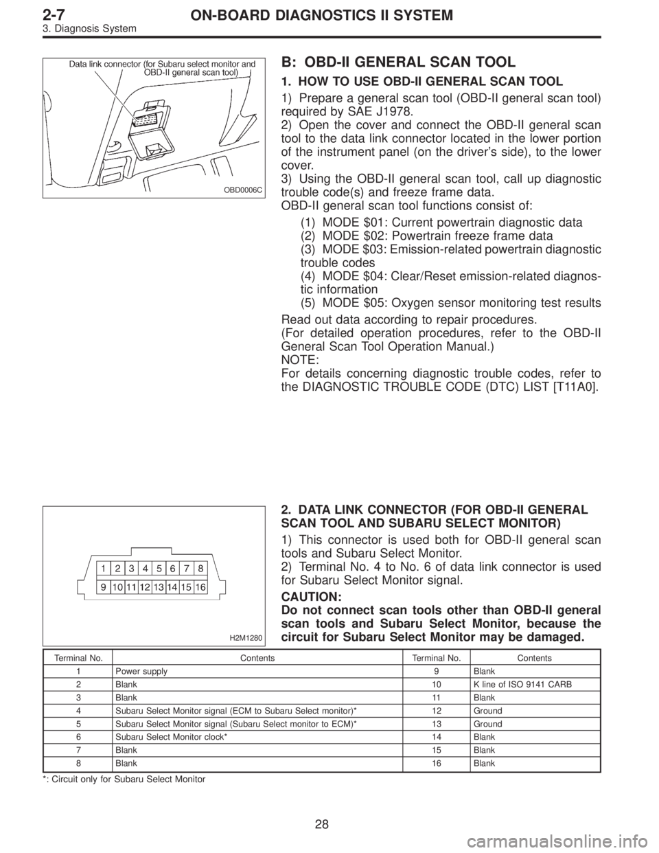
OBD0006C
B: OBD-II GENERAL SCAN TOOL
1. HOW TO USE OBD-II GENERAL SCAN TOOL
1) Prepare a general scan tool (OBD-II general scan tool)
required by SAE J1978.
2) Open the cover and connect the OBD-II general scan
tool to the data link connector located in the lower portion
of the instrument panel (on the driver’s side), to the lower
cover.
3) Using the OBD-II general scan tool, call up diagnostic
trouble code(s) and freeze frame data.
OBD-II general scan tool functions consist of:
(1) MODE $01: Current powertrain diagnostic data
(2) MODE $02: Powertrain freeze frame data
(3) MODE $03: Emission-related powertrain diagnostic
trouble codes
(4) MODE $04: Clear/Reset emission-related diagnos-
tic information
(5) MODE $05: Oxygen sensor monitoring test results
Read out data according to repair procedures.
(For detailed operation procedures, refer to the OBD-II
General Scan Tool Operation Manual.)
NOTE:
For details concerning diagnostic trouble codes, refer to
the DIAGNOSTIC TROUBLE CODE (DTC) LIST [T11A0].
H2M1280
2. DATA LINK CONNECTOR (FOR OBD-II GENERAL
SCAN TOOL AND SUBARU SELECT MONITOR)
1) This connector is used both for OBD-II general scan
tools and Subaru Select Monitor.
2) Terminal No. 4 to No. 6 of data link connector is used
for Subaru Select Monitor signal.
CAUTION:
Do not connect scan tools other than OBD-II general
scan tools and Subaru Select Monitor, because the
circuit for Subaru Select Monitor may be damaged.
Terminal No. Contents Terminal No. Contents
1 Power supply 9 Blank
2 Blank10 K line of ISO 9141 CARB
3 Blank11 Blank
4 Subaru Select Monitor signal (ECM to Subaru Select monitor)* 12 Ground
5 Subaru Select Monitor signal (Subaru Select monitor to ECM)* 13 Ground
6 Subaru Select Monitor clock* 14 Blank
7 Blank15 Blank
8 Blank16 Blank
*: Circuit only for Subaru Select Monitor
28
2-7ON-BOARD DIAGNOSTICS II SYSTEM
3. Diagnosis System