Page 53 of 2248
5. Camshaft
A: REMOVAL
1. RELATED PARTS
1) Remove timing belt, camshaft sprockets and related
parts.
2) Remove valve rocker assembly.
2. CAMSHAFT LH
B2M0384A
1) Remove oil level gauge guide attaching bolt.
2) Remove camshaft support LH.
CAUTION:
Do not damage the camshaft position sensor.
3) Remove O-ring.
4) Remove camshaft LH.
5) Remove oil seal.
CAUTION:
�Do not remove oil seal unless necessary.
�Do not scratch journal surface when removing oil
seal.
33
2-3SERVICE PROCEDURE
5. Camshaft
Page 56 of 2248
C: INSTALLATION
1. CAMSHAFT LH
B2M0384B
Tightening torque: N⋅m (kg-m, ft-lb)
T1: 10 (1.0, 7)
T2: 16 (1.6, 12)
1) Apply a coat of engine oil to camshaft journals and
install camshaft LH.
2) Apply a coat of engine oil or grease to O-ring.
3) Install O-ring to camshaft support.
CAUTION:
Use a new O-ring.
4) Install camshaft support.
G2M0141
5) Apply a coat of grease to oil seal lips and install oil seal
on camshaft support by using ST1 and ST2.
CAUTION:
Use a new oil seal.
ST1 499597000 OIL SEAL GUIDE
ST2 499587100 OIL SEAL INSTALLER
6) Install oil level gauge guide bolt.
36
2-3SERVICE PROCEDURE
5. Camshaft
Page 60 of 2248
2. CYLINDER HEAD
B2M0119A
1) Remove timing belt, camshaft sprocket and related
parts.
2) Remove oil level gauge guide attaching bolt (left hand
only) and oil level gauge guide.
B2M0120A
3) Remove cylinder head bolts in numerical sequence
shown in Figure.
CAUTION:
Leave bolts�
1and�3engaged by three or four threads
to prevent cylinder head from falling.
4) While tapping cylinder head with a plastic hammer,
separate it from cylinder block.
Remove bolts�
1and�3to remove cylinder head.
5) Remove cylinder head gasket.
CAUTION:
Do not scratch the mating surface of cylinder head and
cylinder block.
6) Similarly, remove right side cylinder head.
39
2-3SERVICE PROCEDURE
6. Cylinder Head
Page 70 of 2248
(7) Further tighten all bolts by 80 to 90°in numerical
sequence.
CAUTION:
Ensure that the total“re-tightening angle”[steps (6)
and (7) above] do not exceed 180°.
3) Install oil level gauge guide attaching bolt (left side
only).
4) Install timing belt, camshaft sprocket and related parts.
2. INTAKE MANIFOLD
CAUTION:
Use dry compressed air to remove foreign particles
before installing each solenoid valve and sensor.
1) Install engine coolant pipe.
2) Install intake manifold.
3) Remove ENGINE STAND (ST).
49
2-3SERVICE PROCEDURE
6. Cylinder Head
Page 99 of 2248

2. Engine Noise
Valve lash adjusters may make clicking noise once engine
starts. It is normal if clicking noise ceases after a few min-
utes.
If clicking noise continues after a few minutes, check
engine oil level and add oil if necessary.
Then, do as follows to cease clicking noise.
1) Warm-up engine for five minutes.
2) Turn ignition switch OFF.
3) Connect test mode connector.
4) Start the engine and run it at approximately 2,000 rpm
for twenty minutes.
5) Turn ignition switch OFF.
6) Disconnect test mode connector.
7) Start the engine and check that clicking noise is ceased.
If noise still exists, conduct troubleshooting procedures in
accordance with the following table.
CAUTION:
Do not disconnect spark plug cord while engine is run-
ning.
Type of sound Condition Possible cause
Regular clicking soundSound increases as engine
speed increases.Valve mechanism is defective.
�Broken lash adjuster
�Worn valve rocker
�Worn camshaft
�Broken valve spring
�Worn valve lifter hole
Heavy and dull clankOil pressure is low.�Worn crankshaft main bearing
�Worn connecting rod bearing (big end)
Oil pressure is normal.�Loose flywheel mounting bolts
�Damaged engine mounting
High-pitched clank
(Spark knock)Sound is noticeable when
accelerating with an overload.�Ignition timing advanced
�Accumulation of carbon inside combustion chamber
�Wrong spark plug
�Improper gasoline
Clank when engine speed is
medium (1,000 to 2,000 rpm).Sound is reduced when fuel
injector connector of noisy
cylinder is disconnected.
(NOTE*)�Worn crankshaft main bearing
�Worn bearing at crankshaft end of connecting rod
Knocking sound when engine
is operating under idling speed
and engine is warm.Sound is reduced when fuel
injector connector of noisy
cylinder is disconnected.
(NOTE*)�Worn cylinder liner and piston ring
�Broken or stuck piston ring
�Worn piston pin and hole at piston end of connecting rod
Sound is not reduced if each
fuel injector connector is
disconnected in turn. (NOTE*)�Unusually worn valve lifter
�Worn cam gear
�Worn camshaft journal bore in crankcase
Squeaky sound—�Insufficient generator lubrication
Rubbing sound—�Defective generator brush and rotor contact
Gear scream when starting
engine—�Defective ignition starter switch
�Worn gear and starter pinion
Sound like polishing glass with
a dry cloth—�Loose drive belt
�Defective engine coolant pump shaft
78
2-3DIAGNOSTICS
2. Engine Noise
Page 102 of 2248
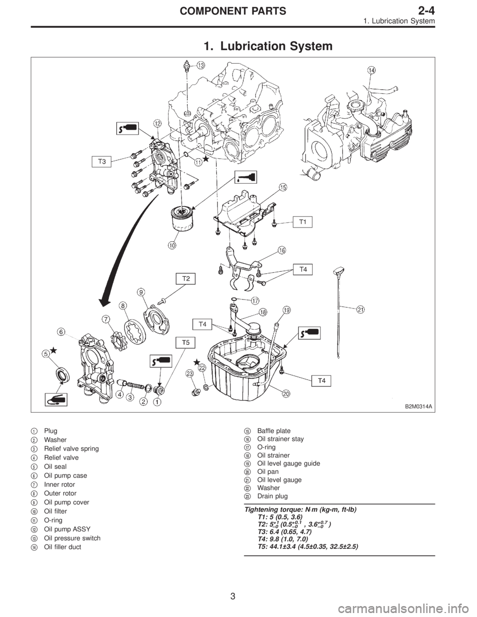
1. Lubrication System
B2M0314A
�1Plug
�
2Washer
�
3Relief valve spring
�
4Relief valve
�
5Oil seal
�
6Oil pump case
�
7Inner rotor
�
8Outer rotor
�
9Oil pump cover
�
10Oil filter
�
11O-ring
�
12Oil pump ASSY
�
13Oil pressure switch
�
14Oil filler duct�
15Baffle plate
�
16Oil strainer stay
�
17O-ring
�
18Oil strainer
�
19Oil level gauge guide
�
20Oil pan
�
21Oil level gauge
�
22Washer
�
23Drain plug
Tightening torque: N⋅m (kg-m, ft-lb)
T1: 5 (0.5, 3.6)
T2: 5
+1
�0(0.5+0.1
�0, 3.6+0.7
�0)
T3: 6.4 (0.65, 4.7)
T4: 9.8 (1.0, 7.0)
T5: 44.1±3.4 (4.5±0.35, 32.5±2.5)
3
2-4COMPONENT PARTS
1. Lubrication System
Page 116 of 2248
 O")
1. Engine Lubrication System
Before troubleshooting, make sure that the engine oil level
is correct and no oil leakage exists.
Trouble Possible cause Corrective action
1. Warning light remains
on.1) Oil pressure switch
failureCracked diaphragm or oil leakage within switch Replace.
Broken spring or seized contacts Replace.
2) Low oil pressureClogged oil filter Replace.
Malfunction of oil by-pass valve of oil filter Clean or replace.
Malfunction of oil relief valve of oil pump Clean or replace.
Clogged oil passage Clean.
Excessive tip clearance and side clearance of oil
pump rotor and gearReplace.
Clogged oil strainer or broken pipe Clean or replace.
3) No oil pressureInsufficient engine oil Replenish.
Broken pipe of oil strainer Replace.
Stuck oil pump rotor Replace.
2. Warning light does not
go on.1) Burn-out bulb Replace.
2) Poor contact of switch contact points Replace.
3) Disconnection of wiring Repair.
3. Warning light flickers
momentarily.1) Poor contact at terminals Repair.
2) Defective wiring harness Repair.
3) Low oil pressureCheck for the same pos-
sible causes as listed in
1.—2)
16
2-4DIAGNOSTICS
1. Engine Lubrication System
Page 252 of 2248

B: INSTALLATION
1. Install engine to transmission.
2. Tighten bolts which hold upper side of transmission to engine.
3. Remove lifting device and wire rope.
4. Remove garage jack.
5. Install pitching stopper.
AT model
6. Install torque converter onto drive plate.
7. Install canister and bracket.
8. Install power steering pump on bracket.
9. Tighten nuts which hold lower side of transmission to engine.
10. Tighten nuts which install front cushion rubber onto cross-
member.
11. Install front exhaust pipe and center exhaust pipe.
12. Connect hoses, connectors and cables.
13. Install air intake system.
�Air intake duct
�Air cleaner element and upper cover.
With A/C
14. Install A/C pressure hoses.
15. Install cooling system.
16. Install battery onto the vehicle, and connect cables.
17. Fill coolant.
18. Check ATF level, and connect if necessary. [AT]
19. Correct power steering oil, and bleed air.
20. Remove front hood stay, and close front hood.
21. Take off the vehicle from lift arms.
�
�
�
�
�
�
�
�
�
�
�
�
18
2-11SERVICE PROCEDURE
2. Engine
![SUBARU LEGACY 1995 Service Repair Manual 5. Camshaft
A: REMOVAL
1. RELATED PARTS
1) Remove timing belt, camshaft sprockets and related
parts.
<Ref. to 2-3 [W3A1].>
2) Remove valve rocker assembly.
<Ref. to 2-3 [W4A0].>
2. CAMSHAFT LH
B2M0384](/manual-img/17/57432/w960_57432-52.png "SUBARU LEGACY 1995 Service Repair Manual 5. Camshaft
A: REMOVAL
1. RELATED PARTS
1) Remove timing belt, camshaft sprockets and related
parts.
<Ref. to 2-3 [W3A1].>
2) Remove valve rocker assembly.
<Ref. to 2-3 [W4A0].>
2. CAMSHAFT LH
B2M0384")

T1: 10 (1.0, 7)
T2: 16 (1.6, 12)
1) Apply a coat of engine oil to camshaft journals and
install camshaft LH.
2) Apply a c")
![SUBARU LEGACY 1995 Service Repair Manual 2. CYLINDER HEAD
B2M0119A
1) Remove timing belt, camshaft sprocket and related
parts.
<Ref. to 2-3 [W3A1].>
2) Remove oil level gauge guide attaching bolt (left hand
only) and oil level gauge guide.
B](/manual-img/17/57432/w960_57432-59.png "SUBARU LEGACY 1995 Service Repair Manual 2. CYLINDER HEAD
B2M0119A
1) Remove timing belt, camshaft sprocket and related
parts.
<Ref. to 2-3 [W3A1].>
2) Remove oil level gauge guide attaching bolt (left hand
only) and oil level gauge guide.
B")
![SUBARU LEGACY 1995 Service Repair Manual (7) Further tighten all bolts by 80 to 90°in numerical
sequence.
CAUTION:
Ensure that the total“re-tightening angle”[steps (6)
and (7) above] do not exceed 180°.
3) Install oil level gauge guide](/manual-img/17/57432/w960_57432-69.png "SUBARU LEGACY 1995 Service Repair Manual (7) Further tighten all bolts by 80 to 90°in numerical
sequence.
CAUTION:
Ensure that the total“re-tightening angle”[steps (6)
and (7) above] do not exceed 180°.
3) Install oil level gauge guide")