Page 137 of 2248

1. Engine Cooling System
Trouble Possible cause Corrective action
Over-heatinga. Insufficient engine coolantReplenish engine coolant, inspect for leakage, and
repair.
b. Loose timing belt Repair or replace timing belt tensioner.
c. Oil on drive belt Replace.
d. Malfunction of thermostat Replace.
e. Malfunction of engine coolant pump Replace.
f. Clogged engine coolant passage Clean.
g. Improper ignition timingInspect and repair ignition control system.
h. Clogged or leaking radiator Clean or repair, or replace.
i. Improper engine oil in engine coolant Replace engine coolant.
j. Air/fuel mixture ratio too leanInspect and repair fuel injection system.
k. Excessive back pressure in exhaust system Clean or replace.
l. Insufficient clearance between piston and cylinder Adjust or replace.
m. Slipping clutch Repair or replace.
n. Dragging brake Adjust.
o. Improper transmission oil Replace.
p. Defective thermostat Replace.
q. Malfunction of electric fanInspect radiator fan relay, engine coolant temperature
sensor or radiator motor and replace there.
Over-coolinga. Atmospheric temperature extremely low Partly cover radiator front area.
b. Defective thermostat Replace.
Engine coolant
leaks.a. Loosened or damaged connecting units on hoses Repair or replace.
b. Leakage from engine coolant pump Replace.
c. Leakage from engine coolant pipe Repair or replace.
d. Leakage around cylinder head gasket Retighten cylinder head bolts or replace gasket.
e. Damaged or cracked cylinder head and crankcase Repair or replace.
f. Damaged or cracked thermostat case Repair or replace.
g. Leakage from radiator Repair or replace.
Noisea. Defective drive belt Replace.
b. Defective radiator fan Replace.
c. Defective engine coolant pump bearing Replace engine coolant pump.
d. Defective engine coolant pump mechanical seal Replace engine coolant pump.
19
2-5DIAGNOSTICS
1. Engine Cooling System
Page 184 of 2248
G6M0095
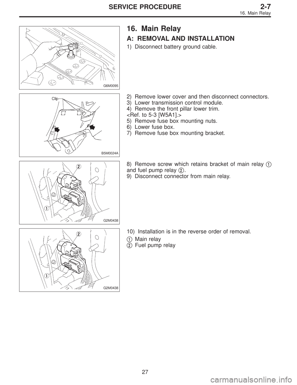
16. Main Relay
A: REMOVAL AND INSTALLATION
1) Disconnect battery ground cable.
B5M0024A
2) Remove lower cover and then disconnect connectors.
3) Lower transmission control module.
4) Remove the front pillar lower trim.
5) Remove fuse box mounting nuts.
6) Lower fuse box.
7) Remove fuse box mounting bracket.
G2M0438
8) Remove screw which retains bracket of main relay�1
and fuel pump relay�2.
9) Disconnect connector from main relay.
G2M0438
10) Installation is in the reverse order of removal.
�
1Main relay
�
2Fuel pump relay
27
2-7SERVICE PROCEDURE
16. Main Relay
Page 185 of 2248
G6M0095
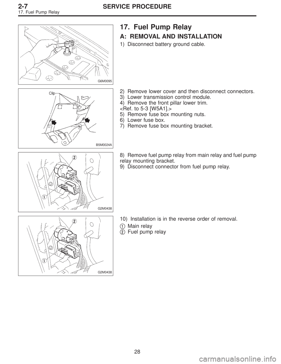
17. Fuel Pump Relay
A: REMOVAL AND INSTALLATION
1) Disconnect battery ground cable.
B5M0024A
2) Remove lower cover and then disconnect connectors.
3) Lower transmission control module.
4) Remove the front pillar lower trim.
5) Remove fuse box mounting nuts.
6) Lower fuse box.
7) Remove fuse box mounting bracket.
G2M0438
8) Remove fuel pump relay from main relay and fuel pump
relay mounting bracket.
9) Disconnect connector from fuel pump relay.
G2M0438
10) Installation is in the reverse order of removal.
�
1Main relay
�
2Fuel pump relay
28
2-7SERVICE PROCEDURE
17. Fuel Pump Relay
Page 194 of 2248
G2M0345
3. Fuel Tank
A: REMOVAL
1) Release fuel pressure.
2) Drain fuel from fuel tank.
G2M0382
3) Remove rear exhaust pipe.
(1) Lift-up the vehicle.
(2) Separate rear exhaust pipe from center exhaust
pipe.
(3) Separate rear exhaust pipe from muffler.
(4) Remove bracket from rubber cushion, and remove
exhaust pipe.
NOTE:
To facilitate the removal of parts, apply a coat of SUBARU
CRC5-56 (Part No. 004301003)
G2M0384
4) Remove muffler assembly.
NOTE:
To facilitate the removal of parts, apply a coat of SUBARU
CRC5-56 (Part No. 004301003)
G3M0059
5) Remove rear differential assembly. (AWD model)
(1) Remove rear axle shafts from rear differential
assembly.
(2) Remove rear differential front cover.
(3) Remove propeller shaft.
(4) Remove lower differential bracket.
(5) Set transmission jack under rear differential.
(6) Remove bolts which install rear differential onto
rear crossmember.
9
2-8SERVICE PROCEDURE
3. Fuel Tank
Page 227 of 2248
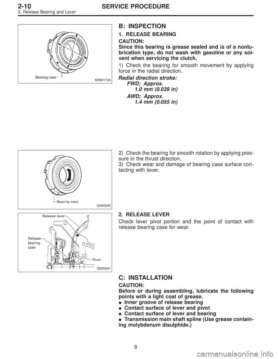
B2M0173A
B: INSPECTION
1. RELEASE BEARING
CAUTION:
Since this bearing is grease sealed and is of a nonlu-
brication type, do not wash with gasoline or any sol-
vent when servicing the clutch.
1) Check the bearing for smooth movement by applying
force in the radial direction.
Radial direction stroke:
FWD; Approx.
1.0 mm (0.039 in)
AWD; Approx.
1.4 mm (0.055 in)
G2M0240
2) Check the bearing for smooth rotation by applying pres-
sure in the thrust direction.
3) Check wear and damage of bearing case surface con-
tacting with lever.
G2M0241
2. RELEASE LEVER
Check lever pivot portion and the point of contact with
release bearing case for wear.
C: INSTALLATION
CAUTION:
Before or during assembling, lubricate the following
points with a light coat of grease.
�Inner groove of release bearing
�Contact surface of lever and pivot
�Contact surface of lever and bearing
�Transmission main shaft spline (Use grease contain-
ing molybdenum disulphide.)
6
2-10SERVICE PROCEDURE
3. Release Bearing and Lever
Page 228 of 2248
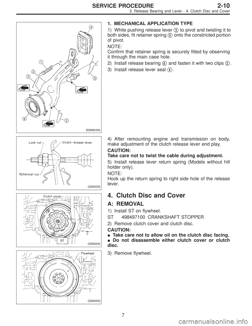
B2M0633A
1. MECHANICAL APPLICATION TYPE
1) While pushing release lever�
3to pivot and twisting it to
both sides, fit retainer spring�
5onto the constricted portion
of pivot.
NOTE:
Confirm that retainer spring is securely fitted by observing
it through the main case hole.
2) Install release bearing�
6and fasten it with two clips�2.
3) Install release lever seal�
4.
G2M0235
4) After remounting engine and transmission on body,
make adjustment of the clutch release lever end play.
CAUTION:
Take care not to twist the cable during adjustment.
5) Install release lever return spring (Models without hill
holder only).
NOTE:
Hook up the return spring to right side hole of the release
lever.
G2M0242
4. Clutch Disc and Cover
A: REMOVAL
1) Install ST on flywheel.
ST 498497100 CRANKSHAFT STOPPER
2) Remove clutch cover and clutch disc.
CAUTION:
�Take care not to allow oil on the clutch disc facing.
�Do not disassemble either clutch cover or clutch
disc.
G2M0243
3) Remove flywheel.
7
2-10SERVICE PROCEDURE
3. Release Bearing and Lever - 4. Clutch Disc and Cover
Page 229 of 2248
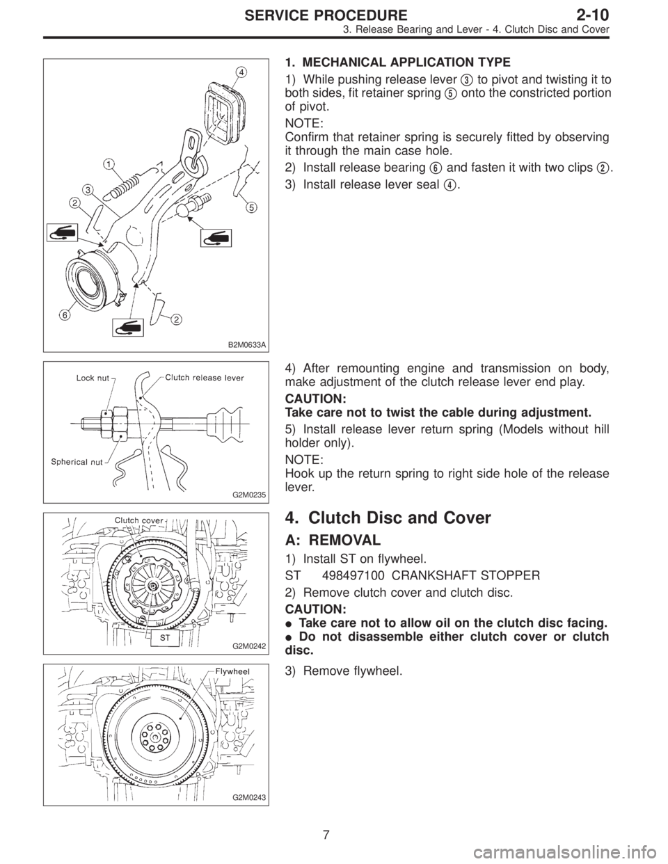
B2M0633A
1. MECHANICAL APPLICATION TYPE
1) While pushing release lever�
3to pivot and twisting it to
both sides, fit retainer spring�
5onto the constricted portion
of pivot.
NOTE:
Confirm that retainer spring is securely fitted by observing
it through the main case hole.
2) Install release bearing�
6and fasten it with two clips�2.
3) Install release lever seal�
4.
G2M0235
4) After remounting engine and transmission on body,
make adjustment of the clutch release lever end play.
CAUTION:
Take care not to twist the cable during adjustment.
5) Install release lever return spring (Models without hill
holder only).
NOTE:
Hook up the return spring to right side hole of the release
lever.
G2M0242
4. Clutch Disc and Cover
A: REMOVAL
1) Install ST on flywheel.
ST 498497100 CRANKSHAFT STOPPER
2) Remove clutch cover and clutch disc.
CAUTION:
�Take care not to allow oil on the clutch disc facing.
�Do not disassemble either clutch cover or clutch
disc.
G2M0243
3) Remove flywheel.
7
2-10SERVICE PROCEDURE
3. Release Bearing and Lever - 4. Clutch Disc and Cover
Page 230 of 2248
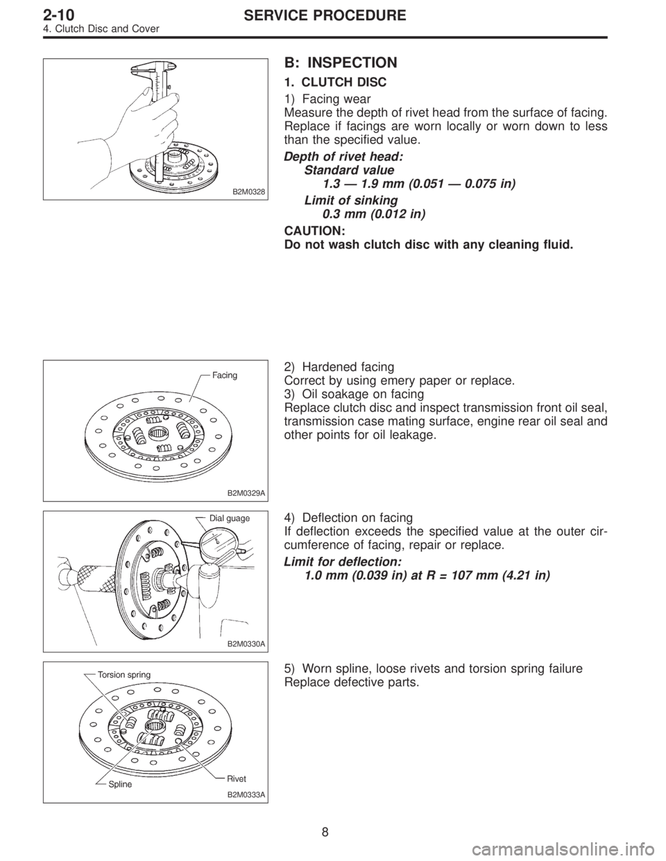
B2M0328
B: INSPECTION
1. CLUTCH DISC
1) Facing wear
Measure the depth of rivet head from the surface of facing.
Replace if facings are worn locally or worn down to less
than the specified value.
Depth of rivet head:
Standard value
1.3—1.9 mm (0.051—0.075 in)
Limit of sinking
0.3 mm (0.012 in)
CAUTION:
Do not wash clutch disc with any cleaning fluid.
B2M0329A
2) Hardened facing
Correct by using emery paper or replace.
3) Oil soakage on facing
Replace clutch disc and inspect transmission front oil seal,
transmission case mating surface, engine rear oil seal and
other points for oil leakage.
B2M0330A
4) Deflection on facing
If deflection exceeds the specified value at the outer cir-
cumference of facing, repair or replace.
Limit for deflection:
1.0 mm (0.039 in) at R = 107 mm (4.21 in)
B2M0333A
5) Worn spline, loose rivets and torsion spring failure
Replace defective parts.
8
2-10SERVICE PROCEDURE
4. Clutch Disc and Cover
![SUBARU LEGACY 1995 Service Repair Manual G2M0345
3. Fuel Tank
A: REMOVAL
1) Release fuel pressure. <Ref. to 2-8 [W1A0].>
2) Drain fuel from fuel tank. <Ref. to 2-8 [W1B0].>
G2M0382
3) Remove rear exhaust pipe.
(1) Lift-up the vehicle.
(2) Se](/manual-img/17/57432/w960_57432-193.png "SUBARU LEGACY 1995 Service Repair Manual G2M0345
3. Fuel Tank
A: REMOVAL
1) Release fuel pressure. <Ref. to 2-8 [W1A0].>
2) Drain fuel from fuel tank. <Ref. to 2-8 [W1B0].>
G2M0382
3) Remove rear exhaust pipe.
(1) Lift-up the vehicle.
(2) Se")