Page 194 of 2248
G2M0345
3. Fuel Tank
A: REMOVAL
1) Release fuel pressure.
2) Drain fuel from fuel tank.
G2M0382
3) Remove rear exhaust pipe.
(1) Lift-up the vehicle.
(2) Separate rear exhaust pipe from center exhaust
pipe.
(3) Separate rear exhaust pipe from muffler.
(4) Remove bracket from rubber cushion, and remove
exhaust pipe.
NOTE:
To facilitate the removal of parts, apply a coat of SUBARU
CRC5-56 (Part No. 004301003)
G2M0384
4) Remove muffler assembly.
NOTE:
To facilitate the removal of parts, apply a coat of SUBARU
CRC5-56 (Part No. 004301003)
G3M0059
5) Remove rear differential assembly. (AWD model)
(1) Remove rear axle shafts from rear differential
assembly.
(2) Remove rear differential front cover.
(3) Remove propeller shaft.
(4) Remove lower differential bracket.
(5) Set transmission jack under rear differential.
(6) Remove bolts which install rear differential onto
rear crossmember.
9
2-8SERVICE PROCEDURE
3. Fuel Tank
Page 195 of 2248
G4M0545
6) Remove rear crossmember. (AWD model)
G2M0353
7) Loosen clamp, and disconnect fuel filler hose from pipe.
8) Loosen clamp, and disconnect air vent hose from air
vent pipe.
�
1Fuel filler hose
�
2Air vent hose
B2M0310A
9) Loosen clip and clamps, and disconnect fuel delivery
hose�
1, return hose�2and evaporation hose�3.
G2M0356
10) While holding fuel tank, remove bolts from bands and
dismount fuel tank.
WARNING:
A helper is required to perform step 10).
B: INSTALLATION
Installation is in the reverse order of removal. Do the fol-
lowing:
1) When installing fuel tank, have a helper hold fuel tank
while installing bands.
2) Before tightening band mounting bolts, connect fuel
system hoses.
10
2-8SERVICE PROCEDURE
3. Fuel Tank
Page 197 of 2248
G3M0059
6) Install rear differential assembly.
G2M0384
7) Install muffler assembly.
G2M0382
8) Install heat sealed cover.
9) Install rear exhaust pipe.
G2M0340
10) Lower the vehicle, and connect connector to fuel
pump.
11) Install access hole lid.
G2M0345
4. Fuel Filler Pipe
A: REMOVAL
1) Release fuel pressure.
2) Drain fuel from fuel tank.
12
2-8SERVICE PROCEDURE
3. Fuel Tank - 4. Fuel Filler Pipe
Page 198 of 2248
G3M0059
6) Install rear differential assembly.
G2M0384
7) Install muffler assembly.
G2M0382
8) Install heat sealed cover.
9) Install rear exhaust pipe.
G2M0340
10) Lower the vehicle, and connect connector to fuel
pump.
11) Install access hole lid.
G2M0345
4. Fuel Filler Pipe
A: REMOVAL
1) Release fuel pressure.
2) Drain fuel from fuel tank.
12
2-8SERVICE PROCEDURE
3. Fuel Tank - 4. Fuel Filler Pipe
Page 202 of 2248
C: INSTALLATION
CAUTION:
�If fuel hoses are damaged at the connecting portion,
replace it with a new one.
�If clamps are badly damaged, replace with new ones.
G2M0347
1) Installation is in the reverse order of removal.
2) Tighten hose clamp screws.
Tightening torque:
1.0
+0.5
0N⋅m (0.1+0.05
0kg-m, 0.7+0.4
0ft-lb)
B2M0048A
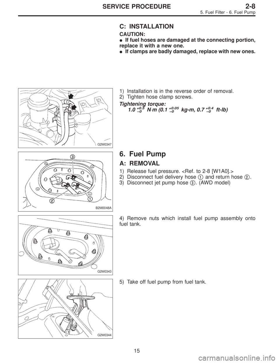
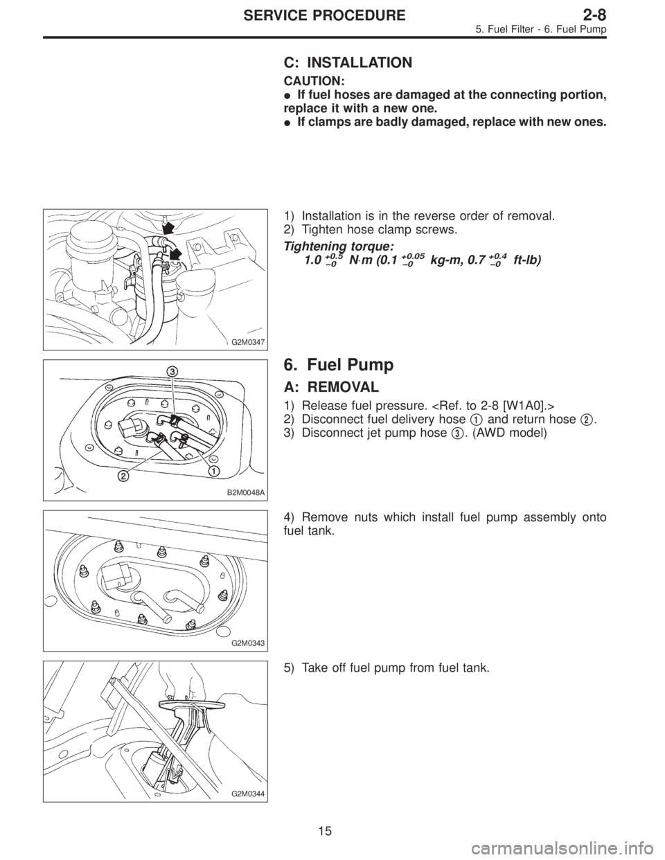
6. Fuel Pump
A: REMOVAL
1) Release fuel pressure.
2) Disconnect fuel delivery hose�
1and return hose�2.
3) Disconnect jet pump hose�
3. (AWD model)
G2M0343
4) Remove nuts which install fuel pump assembly onto
fuel tank.
G2M0344
5) Take off fuel pump from fuel tank.
15
2-8SERVICE PROCEDURE
5. Fuel Filter - 6. Fuel Pump
Page 203 of 2248
C: INSTALLATION
CAUTION:
�If fuel hoses are damaged at the connecting portion,
replace it with a new one.
�If clamps are badly damaged, replace with new ones.
G2M0347
1) Installation is in the reverse order of removal.
2) Tighten hose clamp screws.
Tightening torque:
1.0
+0.5
0N⋅m (0.1+0.05
0kg-m, 0.7+0.4
0ft-lb)
B2M0048A
6. Fuel Pump
A: REMOVAL
1) Release fuel pressure.
2) Disconnect fuel delivery hose�
1and return hose�2.
3) Disconnect jet pump hose�
3. (AWD model)
G2M0343
4) Remove nuts which install fuel pump assembly onto
fuel tank.
G2M0344
5) Take off fuel pump from fuel tank.
15
2-8SERVICE PROCEDURE
5. Fuel Filter - 6. Fuel Pump
Page 206 of 2248
G2M0344
4) Remove nuts which install fuel pump assembly onto
fuel tank.
5) Take off fuel pump assembly.
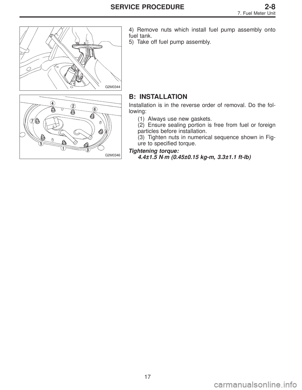
G2M0346
B: INSTALLATION
Installation is in the reverse order of removal. Do the fol-
lowing:
(1) Always use new gaskets.
(2) Ensure sealing portion is free from fuel or foreign
particles before installation.
(3) Tighten nuts in numerical sequence shown in Fig-
ure to specified torque.
Tightening torque:
4.4±1.5 N⋅m (0.45±0.15 kg-m, 3.3±1.1 ft-lb)
17
2-8SERVICE PROCEDURE
7. Fuel Meter Unit
Page 207 of 2248
8. Fuel Delivery, Return and
Evaporation Lines
A: REMOVAL
1) Release fuel pressure.
2) Remove inner trim, insulator and rear seat.
3) Remove fuel delivery pipes and hoses, fuel return pipes
and hoses, and evaporation pipes and hoses.
B2M0050A
�1Canister
�
2Fuel tank
�
3Fuel pump�
4Fuel cut valve (AWD)
�
5Fuel sub meter unit (AWD)
�
6Fuel filter
18
2-8SERVICE PROCEDURE
8. Fuel Delivery, Return and Evaporation Lines
![SUBARU LEGACY 1995 Service Repair Manual G2M0345
3. Fuel Tank
A: REMOVAL
1) Release fuel pressure. <Ref. to 2-8 [W1A0].>
2) Drain fuel from fuel tank. <Ref. to 2-8 [W1B0].>
G2M0382
3) Remove rear exhaust pipe.
(1) Lift-up the vehicle.
(2) Se](/manual-img/17/57432/w960_57432-193.png "SUBARU LEGACY 1995 Service Repair Manual G2M0345
3. Fuel Tank
A: REMOVAL
1) Release fuel pressure. <Ref. to 2-8 [W1A0].>
2) Drain fuel from fuel tank. <Ref. to 2-8 [W1B0].>
G2M0382
3) Remove rear exhaust pipe.
(1) Lift-up the vehicle.
(2) Se")
![SUBARU LEGACY 1995 Service Repair Manual G4M0545
6) Remove rear crossmember. (AWD model)
<Ref. to 4-1 [W11A0].>
G2M0353
7) Loosen clamp, and disconnect fuel filler hose from pipe.
8) Loosen clamp, and disconnect air vent hose from air
vent p](/manual-img/17/57432/w960_57432-194.png "SUBARU LEGACY 1995 Service Repair Manual G4M0545
6) Remove rear crossmember. (AWD model)
<Ref. to 4-1 [W11A0].>
G2M0353
7) Loosen clamp, and disconnect fuel filler hose from pipe.
8) Loosen clamp, and disconnect air vent hose from air
vent p")
![SUBARU LEGACY 1995 Service Repair Manual G3M0059
6) Install rear differential assembly. <Ref. to 3-4 [W2F0].>
G2M0384
7) Install muffler assembly.
G2M0382
8) Install heat sealed cover.
9) Install rear exhaust pipe.
G2M0340
10) Lower the vehi](/manual-img/17/57432/w960_57432-196.png "SUBARU LEGACY 1995 Service Repair Manual G3M0059
6) Install rear differential assembly. <Ref. to 3-4 [W2F0].>
G2M0384
7) Install muffler assembly.
G2M0382
8) Install heat sealed cover.
9) Install rear exhaust pipe.
G2M0340
10) Lower the vehi")
![SUBARU LEGACY 1995 Service Repair Manual G3M0059
6) Install rear differential assembly. <Ref. to 3-4 [W2F0].>
G2M0384
7) Install muffler assembly.
G2M0382
8) Install heat sealed cover.
9) Install rear exhaust pipe.
G2M0340
10) Lower the vehi](/manual-img/17/57432/w960_57432-197.png "SUBARU LEGACY 1995 Service Repair Manual G3M0059
6) Install rear differential assembly. <Ref. to 3-4 [W2F0].>
G2M0384
7) Install muffler assembly.
G2M0382
8) Install heat sealed cover.
9) Install rear exhaust pipe.
G2M0340
10) Lower the vehi")
![SUBARU LEGACY 1995 Service Repair Manual 8. Fuel Delivery, Return and
Evaporation Lines
A: REMOVAL
1) Release fuel pressure. <Ref. to 2-8 [W1A0].>
2) Remove inner trim, insulator and rear seat.
3) Remove fuel delivery pipes and hoses, fuel r](/manual-img/17/57432/w960_57432-206.png "SUBARU LEGACY 1995 Service Repair Manual 8. Fuel Delivery, Return and
Evaporation Lines
A: REMOVAL
1) Release fuel pressure. <Ref. to 2-8 [W1A0].>
2) Remove inner trim, insulator and rear seat.
3) Remove fuel delivery pipes and hoses, fuel r")