Page 937 of 2248
5. TRUNK LID AND REAR GATE
B5M0255A
Unit: mm (in)
20
5-1SERVICE DATA
3. Datum Dimensions
Page 941 of 2248
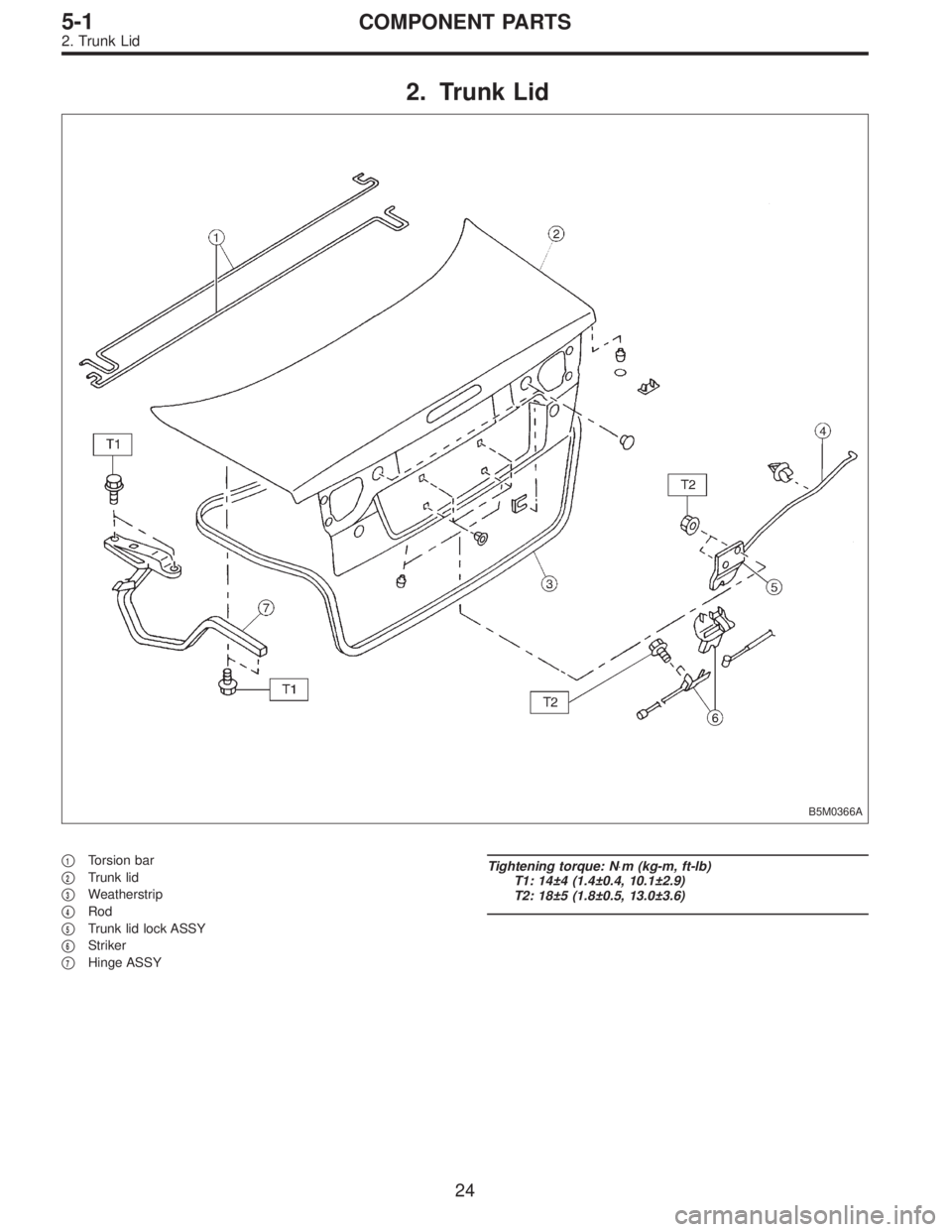
2. Trunk Lid
B5M0366A
�1Torsion bar
�
2Trunk lid
�
3Weatherstrip
�
4Rod
�
5Trunk lid lock ASSY
�
6Striker
�
7Hinge ASSY
Tightening torque: N⋅m (kg-m, ft-lb)
T1: 14±4 (1.4±0.4, 10.1±2.9)
T2: 18±5 (1.8±0.5, 13.0±3.6)
24
5-1COMPONENT PARTS
2. Trunk Lid
Page 950 of 2248
G5M0144
2. Trunk Lid
A: REMOVAL
1. TRUNK LID
1) Open trunk lid.
2) Remove trunk lid mounting bolts and detach trunk lid
from hinges.
G5M0145
2. TORSION BAR
1) Open trunk lid. Remove torsion bars from hinge links
using ST.
ST 927780000 REMOVER
CAUTION:
Be careful because torsion bar quickly swings back
when released.
2) Remove the left and right torsion bars.
WARNING:
Be careful because trunk lid drops under its own
weight when torsion bars are removed.
G5M0146
3. TRUNK LID LOCK ASSEMBLY AND KEY
CYLINDER
1) Remove rod of lock assembly from rod holder of key
lock assembly.
2) Remove nuts which hold lock assembly and remove
lock assembly.
NOTE:
�Always remove rear skirt trim panel beforehand, if so
equipped.
�Be careful not to bend opener cable.
B5M0269A
3) Remove rod holder and detach key cylinder from trunk
lid.
33
5-1SERVICE PROCEDURE
2. Trunk Lid
Page 951 of 2248
 Remove rear seats, center pillar lower cover, floor mat,
rear arch cover and side sill cover (on the driver’s side).
2) Remove all clips which hold cable.
3) Disconnec")
G5M0147
4. TRUNK LID OPENER
1) Remove rear seats, center pillar lower cover, floor mat,
rear arch cover and side sill cover (on the driver’s side).
2) Remove all clips which hold cable.
3) Disconnect cable from pull handle assembly.
4) Remove bolts and detach pull handle assembly.
5) Loosen bolts which hold lock assembly, and remove it.
6) Remove striker from trunk lid.
7) Disconnect cable from striker.
NOTE:
�Be careful not to bend or break cable.
�Basic model vehicles do not have trunk lid opener sys-
tem.
B5M0372A
B: INSTALLATION
Installation is in the reverse order of removal.
CAUTION:
�When installing cover to pull handle assembly,
observe the following:
�Be careful not to catch harness.
�Engage pull handle assembly pawls firmly.
�After installing opener cable, ensure it moves
smoothly.
�Apply a coat of grease to the rotary section of
hinges and contact surfaces of torsion bars.
�Apply grease to sliding surfaces of lock assembly
and striker.
B5M0270A
C: ADJUSTMENT
1. TRUNK LID
1) To adjust left-right lid positioning, loosen bolts which
hold trunk lid to hinges.
2) To adjust up-down lid alignment, place washer(s)
between trunk lid and hinges or move trunk lock assembly
up or down.
34
5-1SERVICE PROCEDURE
2. Trunk Lid
Page 955 of 2248
B5M0377
5. Rear Bumper
A: REMOVAL
1. SEDAN
1) Remove one bolt and one clip from side of bumper.
2) Open trunk lid. Remove trunk trim panel clips and
detach trim.
B5M0378
3) Remove rear bumper beam (upper) attaching nut.
4) Remove bolts from bumper stays.
B5M0280
5) Remove rear bumper assembly.
B5M0377
2. WAGON
1) Remove one bolt and one clip from side of bumper.
2) Open rear gate. Remove rear quarter trim lid.
B5M0379
3) Remove two clips from lower center of bumper.
38
5-1SERVICE PROCEDURE
5. Rear Bumper
Page 1023 of 2248
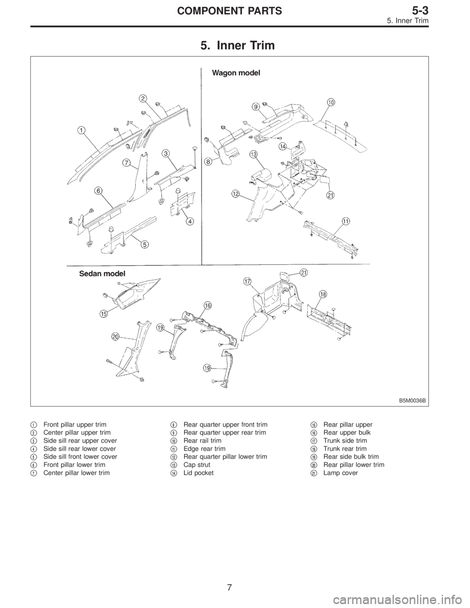
5. Inner Trim
B5M0036B
�1Front pillar upper trim
�
2Center pillar upper trim
�
3Side sill rear upper cover
�
4Side sill rear lower cover
�
5Side sill front lower cover
�
6Front pillar lower trim
�
7Center pillar lower trim�
8Rear quarter upper front trim
�
9Rear quarter upper rear trim
�
10Rear rail trim
�
11Edge rear trim
�
12Rear quarter pillar lower trim
�
13Cap strut
�
14Lid pocket�
15Rear pillar upper
�
16Rear upper bulk
�
17Trunk side trim
�
18Trunk rear trim
�
19Rear side bulk trim
�
20Rear pillar lower trim
�
21Lamp cover
7
5-3COMPONENT PARTS
5. Inner Trim
Page 1096 of 2248
, 100 minutes (AT)
Cold cranking ampere 430 amperes (MT), 490 amperes (AT)
Fuse10 A, 15 A, 20 A
Combination
meterSpeedometer")
1. Body Electrical
A: SPECIFICATIONS
BatteryReserve capacity 82 minutes (MT), 100 minutes (AT)
Cold cranking ampere 430 amperes (MT), 490 amperes (AT)
Fuse10 A, 15 A, 20 A
Combination
meterSpeedometer Electric pulse type
Tachometer Electric impulse type
Water temperature gauge Thermistor cross coil type
Fuel gauge Resistance cross coil type
Charge indicator light 12 V—1.4 W
Brake fluid level warning/parking brake indicator light 12 V—1.4 W
AT oil temperature warning light (AWD only) 12 V—1.4 W
A.B.S. warning light 12 V—1.4 W
CHECK ENGINE warning light
(Malfunction indicator lamp)12 V—1.4 W
Oil pressure warning light 12 V—1.4 W
AIRBAG system warning light 12 V—1.4 W
Low fuel warning light 12 V—3W
FWD indicator light 12 V—1.4 W
TCS warning light 12 V—1.4 W
TCS indicator light 12 V—1.4 W
Turn signal indicator light 12 V—1.4 W (2 pieces)
Seat belt warning light 12 V—1.4 W
Door open warning light 12 V—1.4 W
Headlight beam indicator light 12 V—1.4 W
Meter illumination light12 V—3 W (2 pieces)
12 V—3.4 W (4 pieces)
Headlight 12 V—60/55 W (Halogen)
Front clearance light 12 V—5W
Turn signal lightFront 12 V—21 W
Rear 12 V—21 W
Tail/Stop light 12 V—5/21 W
Back-up light 12 V—21 W
High-mount stop light12 V—18 W (SEDAN), 12 V—13 W
(WAGON)
License plate light 12 V—5W
Room light 12 V—8W
Trunk room light (SEDAN) 12 V—5W
Luggage room light (WAGON) 12 V—5W
Spot light 12 V—8 W (2 pieces)
Glove box light 12 V—3.4 W
Ash tray illumination light 12 V—1.7 W
Selector lever illumination light (AT model) 12 V—1.7 W
2
6-2SPECIFICATIONS
1. Body Electrical
Page 1111 of 2248
 Remove rear trim.
2) Disconnect connector from rear combination light.
3) Remove nuts which secure rea")
B6M0055A
B6M0056A
5. Stop and Tail Light
A: REMOVAL AND INSTALLATION
1. REAR COMBINATION LIGHT
1) Remove rear trim.
2) Disconnect connector from rear combination light.
3) Remove nuts which secure rear combination light.
Tightening torque:
2.5±0.5 N⋅m (0.25±0.05 kg-m, 1.8±0.4 ft-lb)
4) Attach adhesive cloth tape to body area around rear
combination light.
5) Using a standard screwdriver, carefully pry rear combi-
nation light off and away from the vehicle.
CAUTION:
�Do not pry rear combination light forcefully as this
may scratch vehicle body.
�Remove all traces of adhesive tape from body before
installation.
�Attach butyl rubber tape to back of rear combination
light before installing rear combination light on body
for sealing purposes.
B6M0057A
B6M0058A
2. REAR FINISHER
1) Remove trunk lid trim (SEDAN) or rear gate trim
(WAGON).
2) Disconnect connectors from rear finisher.
3) Remove rear wiper motor (WAGON).
4) Remove nuts which secure rear finisher.
Tightening torque:
2.5±0.5 N⋅m (0.25±0.05 kg-m, 1.8±0.4 ft-lb)
5) Attach adhesive cloth tape to body area around rear
finisher.
6) Using a standard screwdriver, carefully pry rear finisher
off and away from the vehicle.
CAUTION:
Do not pry rear finisher forcefully as this may scratch
vehicle body.
14
6-2SERVICE PROCEDURE
5. Stop and Tail Light

20
5-1SERVICE DATA
3. Datum Dimensions")
 Open trunk lid.
2) Remove trunk lid mounting bolts and detach trunk lid
from hinges.
G5M0145
2. TORSION BAR
1) Open trunk lid. Remove torsion bars from")
 Remove one bolt and one clip from side of bumper.
2) Open trunk lid. Remove trunk trim panel clips and
detach trim.
B5M0378
3) Remove rear bumper beam (up")