Page 186 of 2248
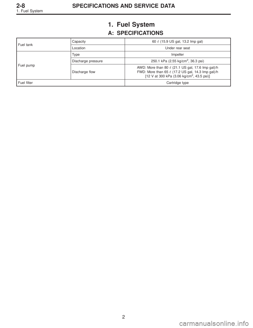
1. Fuel System
A: SPECIFICATIONS
Fuel tankCapacity 60�(15.9 US gal, 13.2 Imp gal)
Location Under rear seat
Fuel pumpType Impeller
Discharge pressure 250.1 kPa (2.55 kg/cm
2, 36.3 psi)
Discharge flowAWD: More than 80�(21.1 US gal, 17.6 Imp gal)/h
FWD: More than 65�(17.2 US gal, 14.3 Imp gal)/h
[12 V at 300 kPa (3.06 kg/cm
2, 43.5 psi)]
Fuel filterCartridge type
2
2-8SPECIFICATIONS AND SERVICE DATA
1. Fuel System
Page 190 of 2248
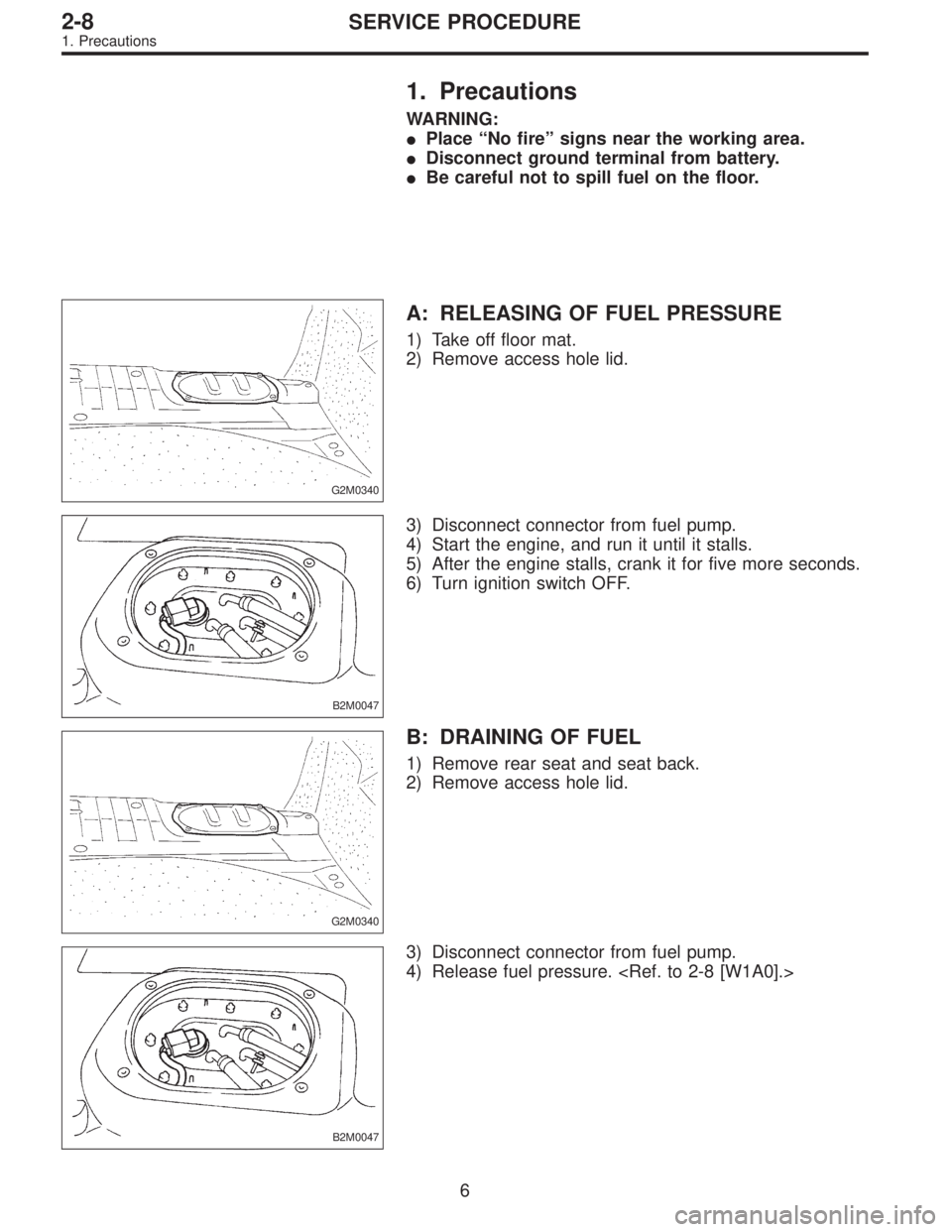
1. Precautions
WARNING:
�Place “No fire” signs near the working area.
�Disconnect ground terminal from battery.
�Be careful not to spill fuel on the floor.
G2M0340
A: RELEASING OF FUEL PRESSURE
1) Take off floor mat.
2) Remove access hole lid.
B2M0047
3) Disconnect connector from fuel pump.
4) Start the engine, and run it until it stalls.
5) After the engine stalls, crank it for five more seconds.
6) Turn ignition switch OFF.
G2M0340
B: DRAINING OF FUEL
1) Remove rear seat and seat back.
2) Remove access hole lid.
B2M0047
3) Disconnect connector from fuel pump.
4) Release fuel pressure.
6
2-8SERVICE PROCEDURE
1. Precautions
Page 207 of 2248
8. Fuel Delivery, Return and
Evaporation Lines
A: REMOVAL
1) Release fuel pressure.
2) Remove inner trim, insulator and rear seat.
3) Remove fuel delivery pipes and hoses, fuel return pipes
and hoses, and evaporation pipes and hoses.
B2M0050A
�1Canister
�
2Fuel tank
�
3Fuel pump�
4Fuel cut valve (AWD)
�
5Fuel sub meter unit (AWD)
�
6Fuel filter
18
2-8SERVICE PROCEDURE
8. Fuel Delivery, Return and Evaporation Lines
Page 209 of 2248
G2M0373
9. Roll Over Valve
A: REMOVAL
1) Lift up the vehicle.
2) Remove roll over valve with bracket.
3) Disconnect hoses from roll over valve, and remove it
from bracket.
G2M0374
B: INSPECTION
1) Connect hoses to roll over valve as shown in Figure.
2) While blowing through open end of hose, tilt valve at
least 90° left and right from normal position.
3) Ensure that there is no air flow when hose is tilted
greater than 90°.
G2M0373
C: INSTALLATION
Installation is in the reverse order of removal.
CAUTION:
�Do not install top side of valve down.
�Before installing bracket on body, securely fit con-
cave part of bracket to hole in body.
G6M0095
10. Fuel Sub Meter Unit (AWD model
only)
A: REMOVAL AND INSTALLATION
1) Disconnect battery ground cable.
G2M0863
2) Remove rear seat.
3) Remove service hole cover.
20
2-8SERVICE PROCEDURE
9. Roll Over Valve - 10. Fuel Sub Meter Unit (Turbo model only)
Page 210 of 2248
G2M0373
9. Roll Over Valve
A: REMOVAL
1) Lift up the vehicle.
2) Remove roll over valve with bracket.
3) Disconnect hoses from roll over valve, and remove it
from bracket.
G2M0374
B: INSPECTION
1) Connect hoses to roll over valve as shown in Figure.
2) While blowing through open end of hose, tilt valve at
least 90° left and right from normal position.
3) Ensure that there is no air flow when hose is tilted
greater than 90°.
G2M0373
C: INSTALLATION
Installation is in the reverse order of removal.
CAUTION:
�Do not install top side of valve down.
�Before installing bracket on body, securely fit con-
cave part of bracket to hole in body.
G6M0095
10. Fuel Sub Meter Unit (AWD model
only)
A: REMOVAL AND INSTALLATION
1) Disconnect battery ground cable.
G2M0863
2) Remove rear seat.
3) Remove service hole cover.
20
2-8SERVICE PROCEDURE
9. Roll Over Valve - 10. Fuel Sub Meter Unit (Turbo model only)
Page 456 of 2248
G3M0493
15. Transfer Clutch
A: DISASSEMBLY
1) Remove the seal ring.
CAUTION:
Be careful not to damage the seal ring.
G3M0494
2) Using a press and ST, remove the ball bearing.
ST 498077000 REMOVER
CAUTION:
Do not reuse the bearing.
G3M0495
3) Remove the snap ring, and take out the pressure plate,
drive plates, and driven plates.
G3M0496
4) Remove the snap ring with ST1, ST2 and ST3, and take
out the spring retainer.
ST1 399893600 PLIERS
ST2 398673600 COMPRESSOR
ST3 498627000 SEAT
G3M0497
5) Apply compressed air to the rear drive shaft to remove
the piston.
109
3-2SERVICE PROCEDURE
15. Transfer Clutch
Page 504 of 2248
 Turn ST1 with hand to make it seated, and tighten
drive pinion nut while measuring the preload with spring
balance. Select preload adjusting washer and spacer
so that the specified preload")
G3M1038
(4) Turn ST1 with hand to make it seated, and tighten
drive pinion nut while measuring the preload with spring
balance. Select preload adjusting washer and spacer
so that the specified preload is obtained when nut is
tightened to the specified torque with ST2.
CAUTION:
Use a new lock nut.
NOTE:
�Be careful not to give excessive preload.
G3M0718
�When tightening the drive pinion nut, lock ST1 with ST2
as shown in the figure.
ST1 398507704 BLOCK
ST2 398507702 DUMMY SHAFT
ST3 498427200 FLANGE WRENCH
Tightening Torque:
181±15 N⋅m (18.5±1.5 kg-m, 134±11 ft-lb)
G3M0082
Front and rear bearing preload
For new bearing:
17.7—25.5 N (1.8—2.6 kg, 4.0—5.7 lb)
at companion flange bolt hole
�Preload adjusting washer lengthPart No. Length mm (in)
383705200
383715200
383725200
383735200
383745200
383755200
383765200
383775200
383785200
383795200
383805200
383815200
383825200
383835200
3838452002.59 (0.1020)
2.57 (0.1012)
2.55 (0.1004)
2.53 (0.0996)
2.51 (0.0988)
2.49 (0.0980)
2.47 (0.0972)
2.45 (0.0965)
2.43 (0.0957)
2.41 (0.0949)
2.39 (0.0941)
2.37 (0.0933)
2.35 (0.0925)
2.33 (0.0917)
2.31 (0.0909)
�Preload adjusting spacer length383695201
383695202
383695203
383695204
383695205
38369520656.2 (2.213)
56.4 (2.220)
56.6 (2.228)
56.8 (2.236)
57.0 (2.244)
57.2 (2.252)
28
3-4SERVICE PROCEDURE
2. Rear Differential
Page 516 of 2248

1. Rear Differential
Symptom and possible cause Remedy
1. Oil leakage
�
1Worn, scratched, or incorrectly seated front or side oil seal.
Scored, battered, or excessively worn sliding surface of com-
panion flange.Repair or replace.
�
2Clogged or damaged air breather. Clean, repair or replace.
�
3Loose bolts on differential spindle or side retainer, or incor-
rectly fitted O-ring.Tighten bolts to specified torque. Replace O-ring.
�
4Loose rear cover attaching bolts or damaged gasket. Tighten bolts to specified torque. Replace gasket and apply liquid
packing.
�
5Loose oil filler or drain plug. Retighten and apply liquid packing.
�
6Wear, damage or incorrectly fitting for spindle, side retainer
and oil seal.Repair or replace.
2. Seizure
Seized or damaged parts should be replaced, and also other parts should be thoroughly checked for any defect and should be
repaired or replaced as required.
�
1Insufficient backlash for hypoid gear. Readjust or replace.
�
2Excessive preload for side, rear, or front bearing. Readjust or replace.
�
3Insufficient or improper oil used. Replace seized part and fill with specified oil to specified level.
3. Damage
Damaged parts should be replaced, and also other parts should be thoroughly checked for any defect and should be repaired or
replaced as required.
�
1Improper backlash for hypoid gear. Replace.
�
2Insufficient or excessive preload for side, rear, or front bear-
ing.Readjust or replace.
�
3Excessive backlash for differential gear. Replace gear or thrust washer.
�
4Loose bolts and nuts such as crown gear bolt. Retighten.
�
5Damage due to overloading. Replace.
4. Noises when starting or shifting gears
Noises may be caused by differential assembly, universal joint, wheel bearing, etc. Find out what is actually making noise before dis-
assembly.
�
1Excessive backlash for hypoid gear. Readjust.
�
2Excessive backlash for differential gear. Replace gear or thrust washer.
�
3Insufficient preload for front or rear bearing. Readjust.
�
4Loose drive pinion nut. Tighten to specified torque.
�
5Loose bolts and nuts such as side bearing retainer attaching
bolt.Tighten to specified torque.
40
3-4DIAGNOSTICS
1. Rear Differential
![SUBARU LEGACY 1995 Service Repair Manual 8. Fuel Delivery, Return and
Evaporation Lines
A: REMOVAL
1) Release fuel pressure. <Ref. to 2-8 [W1A0].>
2) Remove inner trim, insulator and rear seat.
3) Remove fuel delivery pipes and hoses, fuel r](/manual-img/17/57432/w960_57432-206.png "SUBARU LEGACY 1995 Service Repair Manual 8. Fuel Delivery, Return and
Evaporation Lines
A: REMOVAL
1) Release fuel pressure. <Ref. to 2-8 [W1A0].>
2) Remove inner trim, insulator and rear seat.
3) Remove fuel delivery pipes and hoses, fuel r")
 Lift up the vehicle.
2) Remove roll over valve with bracket.
3) Disconnect hoses from roll over valve, and remove it
from bracket.
G2M0374
B: INSPECTION
1) Con")
 Lift up the vehicle.
2) Remove roll over valve with bracket.
3) Disconnect hoses from roll over valve, and remove it
from bracket.
G2M0374
B: INSPECTION
1) Con")
 Remove the seal ring.
CAUTION:
Be careful not to damage the seal ring.
G3M0494
2) Using a press and ST, remove the ball bearing.
ST 498077000 REMOVER
CAUT")