Page 18 of 2248
 Warm-up the engine.
2) Disconnect the brake vacuum hose and install the
vacuum gauge to the hose fitting on the manifold.
G2M0099
3) Keep the engine at the")
5. Intake Manifold Vacuum
A: MEASUREMENT
1) Warm-up the engine.
2) Disconnect the brake vacuum hose and install the
vacuum gauge to the hose fitting on the manifold.
G2M0099
3) Keep the engine at the idle speed and read the vacuum
gauge indication.
By observing the gauge needle movement, the internal
condition of the engine can be diagnosed as described
below.
Vacuum pressure (at idling, A/C“OFF”):
Less than �60.0 kPa
(�450 mmHg, �17.72 inHg)
Diagnosis of engine condition by measurement of manifold vacuum
Vacuum gauge indication Possible engine condition
1. Needle is steady but lower than normal position. This
tendency becomes more evident as engine temperature
rises.Leakage around intake manifold gasket or disconnection or
damaged vacuum hose
2. When engine speed is reduced slowly from higher speed,
needle stops temporarily when it is lowering or becomes
steady above normal position.Back pressure too high, or exhaust system clogged
3. Needle intermittently drops to position lower than normal
position.Leakage around cylinder
4. Needle drops suddenly and intermittently from normal
position.Sticky valves
5. When engine speed is gradually increased, needle begins
to vibrate rapidly at certain speed, and then vibration
increases as engine speed increases.Weak or broken valve springs
6. Needle vibrates above and below normal position in narrow
range.Defective ignition system or throttle chamber idle adjustment
6
2-2
5. Intake Manifold Vacuum
Page 137 of 2248

1. Engine Cooling System
Trouble Possible cause Corrective action
Over-heatinga. Insufficient engine coolantReplenish engine coolant, inspect for leakage, and
repair.
b. Loose timing belt Repair or replace timing belt tensioner.
c. Oil on drive belt Replace.
d. Malfunction of thermostat Replace.
e. Malfunction of engine coolant pump Replace.
f. Clogged engine coolant passage Clean.
g. Improper ignition timingInspect and repair ignition control system.
h. Clogged or leaking radiator Clean or repair, or replace.
i. Improper engine oil in engine coolant Replace engine coolant.
j. Air/fuel mixture ratio too leanInspect and repair fuel injection system.
k. Excessive back pressure in exhaust system Clean or replace.
l. Insufficient clearance between piston and cylinder Adjust or replace.
m. Slipping clutch Repair or replace.
n. Dragging brake Adjust.
o. Improper transmission oil Replace.
p. Defective thermostat Replace.
q. Malfunction of electric fanInspect radiator fan relay, engine coolant temperature
sensor or radiator motor and replace there.
Over-coolinga. Atmospheric temperature extremely low Partly cover radiator front area.
b. Defective thermostat Replace.
Engine coolant
leaks.a. Loosened or damaged connecting units on hoses Repair or replace.
b. Leakage from engine coolant pump Replace.
c. Leakage from engine coolant pipe Repair or replace.
d. Leakage around cylinder head gasket Retighten cylinder head bolts or replace gasket.
e. Damaged or cracked cylinder head and crankcase Repair or replace.
f. Damaged or cracked thermostat case Repair or replace.
g. Leakage from radiator Repair or replace.
Noisea. Defective drive belt Replace.
b. Defective radiator fan Replace.
c. Defective engine coolant pump bearing Replace engine coolant pump.
d. Defective engine coolant pump mechanical seal Replace engine coolant pump.
19
2-5DIAGNOSTICS
1. Engine Cooling System
Page 161 of 2248
B2M0342
12) Disconnect brake booster hose.
B2M0343
13) Remove EGR pipe.
G2M0370
14) Disconnect canister hose from pipe.
B2M0019
15) Disconnect engine harness connectors from bulkhead
harness connectors.
B2M0345A
16) Disconnect connectors from engine coolant tempera-
ture sensor�
1and thermometer�2.
10
2-7SERVICE PROCEDURE
4. Intake Manifold
Page 166 of 2248
B2M0019
8) Connect engine harness connector to bulkhead har-
ness connectors.
G2M0370
9) Connect canister hoses.
B2M0342
10) Connect brake booster vacuum hose.
H2M1259A
11) Connect engine coolant hose�1to idle air control sole-
noid valve.
12) Connect air by-pass hose�
2to idle air control solenoid
valve.
H2M1246
13) Connect engine coolant hoses to throttle body.
15
2-7SERVICE PROCEDURE
4. Intake Manifold
Page 233 of 2248
")
1. Clutch System
Condition Possible cause and testing Corrective action
1. Clutch slip-
pageIt is hard to perceive clutch slippage in the early stage, but pay attention to the following symptoms.
(a) Engine revs up when shifting.
(b) High speed driving is impossible; especially rapid acceleration impossible and vehicle speed does not increase in
proportion to an increase in engine speed.
(c) Power falls, particularly when ascending a slope, and there is a smell of burning of the clutch facing.
�Method of testing: Put the vehicle in stationary condition with parking brake fully applied. Disengage the clutch and
shift the transmission gear into the first. Gradually allow the clutch to engage while gradually increasing the engine
speed. The clutch function is satisfactory if the engine stalls. However, the clutch is slipping if the vehicle does not
start off and the engine does not stall.
(a) No clutch pedal play Readjust.
(b) No release lever end play Readjust.
(c) Clutch facing smeared by oil Replace.
(d) Worn clutch facing Replace.
(e) Deteriorated diaphragm spring Replace.
(f ) Distorted pressure plate or flywheel Correct or replace.
(g) Defective release bearing holder Correct or replace.
(h) Defective pedal and cable system Correct or replace.
2. Clutch
drags.As a symptom of this trouble, a harsh scratching noise develops and control becomes quite difficult when shifting
gears. The symptom becomes more apparent when shifting into the first gear. However, because much trouble of the
this sort is due to defective synchronization mechanism, carry out the test as described after.
�Method of testing: Refer to DIAGNOSTIC DIAGRAM on page after.
It may be judged as insufficient disengagement of clutch if any noise occurs during this test.
(a) Excessive clutch pedal play Readjust.
(b) Excessive clutch release lever play Readjust.
(c) Worn or rusty clutch disc hub spline Replace clutch disc.
(d) Excessive deflection of clutch disc facing Correct or replace.
(e) Seized crankshaft pilot needle bearing Replace.
(f ) Malfunction of pedal and cable system Correct or replace.
(g) Cracked clutch disc facing Replace.
(h) Sticked clutch disc (smeared by oil or water) Replace.
3. Clutch chat-
ters.Clutch chattering is an unpleasant vibration to the whole body when the vehicle is just started with clutch partially
engaged.
(a) Improper clutch cable routing Correct.
(b) Adhesion of oil on the facing Replace clutch disc.
(c) Weak or broken torsion spring Replace clutch disc.
(d) Defective facing contact or excessive disc Replace clutch disc defection.
(e) Warped pressure plate or flywheel Correct or replace.
(f ) Loose disc rivets Replace clutch disc.
(g) Loose engine mounting Retighten or replace mounting.
(h) Improper adjustment of pitching stopper Adjustment.
11
2-10DIAGNOSTICS
1. Clutch System
Page 247 of 2248
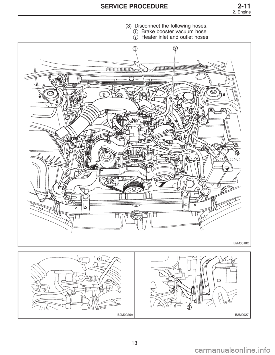
(3) Disconnect the following hoses.
�
1Brake booster vacuum hose
�
2Heater inlet and outlet hoses
B2M0018C
B2M0026AB2M0027
13
2-11SERVICE PROCEDURE
2. Engine
Page 256 of 2248
11) Install front exhaust pipe and center exhaust pipe.
12) Connect hoses, connectors and cables.
(1) Connect the following hoses.
�Fuel delivery hose, return hose and evaporation
hose
�Heater inlet and outlet hoses
�Brake booster vacuum hose
(2) Connect the following connectors.
�Engine ground terminal
�Engine harness connectors
�Front oxygen sensor connector
�Rear oxygen sensor connector
�Alternator connector and terminal
�A/C compressor connectors (With A/C)
(3) Connect the following cables.
�Accelerator cable
�Cruise control cables (With cruise control)
�Clutch cable
�Clutch release spring
CAUTION:
After connecting each cable, adjust them.
G2M0271
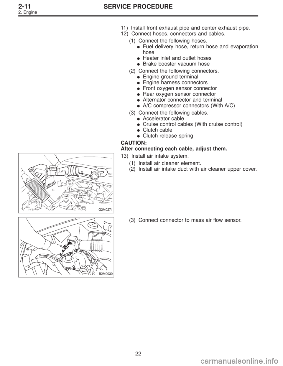
13) Install air intake system.
(1) Install air cleaner element.
(2) Install air intake duct with air cleaner upper cover.
B2M0030
(3) Connect connector to mass air flow sensor.
22
2-11SERVICE PROCEDURE
2. Engine
Page 346 of 2248

1. Automatic Transmission and
Differential
A: SPECIFICATIONS
Torque
converter
clutchTypeSymmetric, 3 element, single stage, 2 phase torque converter
clutch coupling
Stall torque ratio 2.1 — 2.3
Nominal diameter 236 mm (9.29 in)
Stall speed (at sea level) 2,300 — 2,700 rpm
One-way clutch Sprague type one-way clutch
Automatic
transmis-
sionTransmis-
sionType 4-forward, 1-reverse, double-row planetary gears
Control elementMulti-plate clutch 4 sets
Multi-plate brake 1 set
Band brake 1 set
One-way clutch (sprague type) 2 sets
Gear ratio1st 2.785
2nd 1.545
3rd 1.000
4th 0.694
Reverse 2.272
Tooth number of planetary gearFront sun gear 33
Front pinion 21
Front internal gear 75
Rear sun gear 42
Rear pinion 17
Rear internal gear 75
Selector positionP (Park)Transmission in neutral, output
member immovable, and engine
start possible
R (Reverse)Transmission in reverse for
backing
N (Neutral)Transmission in neutral, and
engine start possible
D (Drive)Automatic gear change
1st
+
,2nd+
,3rd+
,4th
3 (3rd)Automatic gear change
1st
+
,2nd+
,3rd+4th
2 (2nd)2nd gear locked
(Deceleration possible
4th,3rd,2nd)
1 (1st)1st gear locked
(Deceleration possible
4th,3rd,2nd,1st)
Control method Hydraulic remote control
2
3-2SPECIFICATIONS AND SERVICE DATA
1. Automatic Transmission and Differential
 Disconnect brake booster hose.
B2M0343
13) Remove EGR pipe.
G2M0370
14) Disconnect canister hose from pipe.
B2M0019
15) Disconnect engine harness connectors from bulkhead
harness connector")
 Connect engine harness connector to bulkhead har-
ness connectors.
G2M0370
9) Connect canister hoses.
B2M0342
10) Connect brake booster vacuum hose.
H2M1259A
11) Connect engine coolant hose")