Page 1308 of 2248
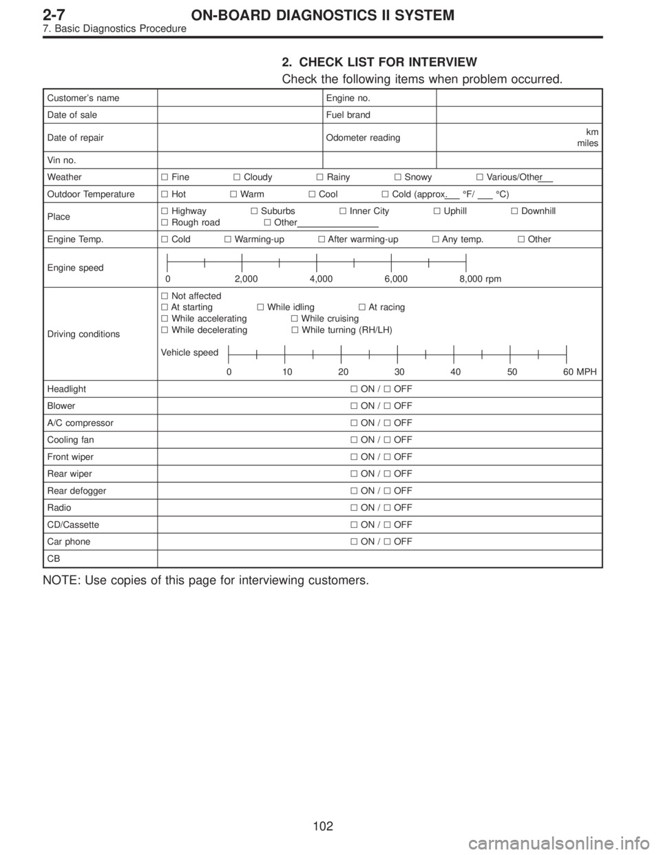
2. CHECK LIST FOR INTERVIEW
Check the following items when problem occurred.
Customer’s name Engine no.
Date of sale Fuel brand
Date of repair Odometer readingkm
miles
Vin no.
Weather�Fine�Cloudy�Rainy�Snowy�Various/Other
Outdoor Temperature�Hot�Warm�Cool�Cold (approx.°F/°C)
Place�Highway�Suburbs�Inner City�Uphill�Downhill
�Rough road�Other
Engine Temp.�Cold�Warming-up�After warming-up�Any temp.�Other
Engine speed
0 2,000 4,000 6,000 8,000 rpm
Driving conditions�Not affected
�At starting�While idling�At racing
�While accelerating�While cruising
�While decelerating�While turning (RH/LH)
Vehicle speed
0 10203040 5060MPH
Headlight�ON /�OFF
Blower�ON /�OFF
A/C compressor�ON /�OFF
Cooling fan�ON /�OFF
Front wiper�ON /�OFF
Rear wiper�ON /�OFF
Rear defogger�ON /�OFF
Radio�ON /�OFF
CD/Cassette�ON /�OFF
Car phone�ON /�OFF
CB
NOTE: Use copies of this page for interviewing customers.
102
2-7ON-BOARD DIAGNOSTICS II SYSTEM
7. Basic Diagnostics Procedure
Page 1678 of 2248
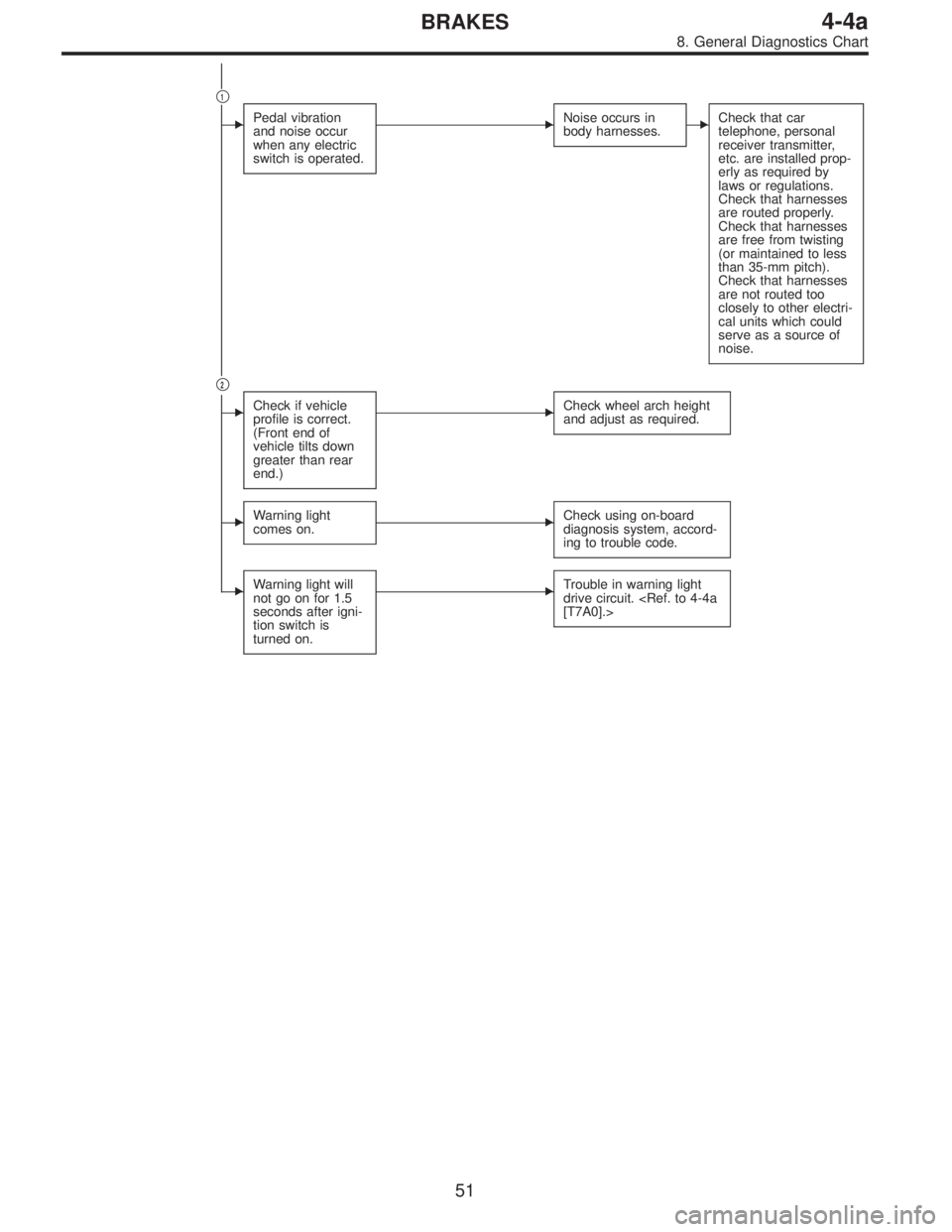
�1
�Pedal vibration
and noise occur
when any electric
switch is operated.�Noise occurs in
body harnesses.�Check that car
telephone, personal
receiver transmitter,
etc. are installed prop-
erly as required by
laws or regulations.
Check that harnesses
are routed properly.
Check that harnesses
are free from twisting
(or maintained to less
than 35-mm pitch).
Check that harnesses
are not routed too
closely to other electri-
cal units which could
serve as a source of
noise.
�2
�Check if vehicle
profile is correct.
(Front end of
vehicle tilts down
greater than rear
end.)�Check wheel arch height
and adjust as required.
�Warning light
comes on.�Check using on-board
diagnosis system, accord-
ing to trouble code.
�Warning light will
not go on for 1.5
seconds after igni-
tion switch is
turned on.�Trouble in warning light
drive circuit.
[T7A0].>
51
4-4aBRAKES
8. General Diagnostics Chart
Page 1726 of 2248
5. CHECK SOURCES OF SIGNAL NOISE.
1) Check that the mobile phone, personal radio and other
wireless apparatus are correctly installed.
2) Check that the antenna and other possible noise
sources are distant enough from the sensor harness.
3) Check that the sealed wires of the front harness sensor
(in the engine room) are securely grounded.
4) Check that between ABS/TCS control module and the
rear sensor harness has the correct twist pitch.
Twist pitch:
25 mm (0.98 in) or less
6. CHECK HYDRAULIC UNIT OPERATIONS.
1) Operate the ABS sequence control and check that the
brake fluid pressure at the malfunctioning brake line
increases and decreases properly.
45
4-4bBRAKES
8. Diagnostics Chart with Trouble Code
 Check that the mobile phone, personal radio and other
wireless apparatus are correctly installed.
2) Check that the antenna and other possible noise
sources are di")