Page 19 of 2248
G2M0088
6. Engine Oil Pressure
A: MEASUREMENT
1) Remove generator from bracket.
(1) Disconnect connector and terminal from generator.
G2M0089
(2) Remove V-belt cover.
(3) Loosen lock bolt and slider bolt, and remove V-belt
for generator.
G2M0090
(4) Remove generator lock bolt.
(5) Remove bolt which install generator on bracket.
G2M0091
2) Disconnect connector from oil pressure switch.
3) Remove oil pressure switch from engine cylinder block.
7
2-2
6. Engine Oil Pressure
Page 20 of 2248
G2M0093
4) Connect oil pressure gauge hose to cylinder block.
5) Start the engine, and measure oil pressure.
Oil pressure:
98 kPa (1.0 kg/cm
2,14 psi) or more at 800 rpm
294 kPa (3.0 kg/cm2, 43 psi) or more at 5,000 rpm
CAUTION:
�If oil pressure is out of specification, check oil
pump, oil filter and lubrication line.
�If oil pressure warning light is turned ON and oil
pressure is in specification, replace oil pressure
switch.
NOTE:
The specified data is based on an engine oil temperature
of 80°C (176°F).
6) After measuring oil pressure, install oil pressure switch.
Tightening torque:
25±3 N⋅m (2.5±0.3 kg-m, 18.1±2.2 ft-lb)
7) Install generator and V-belt in the reverse order of
removal, and adjust the V-belt deflection.
8
2-2
6. Engine Oil Pressure
Page 21 of 2248
1. Engine
A: SPECIFICATIONS
EngineModel2200 cc
TypeHorizontally opposed, liquid cooled, 4-cylinder, 4-stroke
gasoline engine
Valve arrangement Belt driven, single over-head camshaft, 4-valve/cylinder
Bore x Stroke mm (in) 96.9 x 75.0 (3.815 x 2.953)
Displacement cm
3(cu in) 2,212 (135.0)
Compression ratio9.5
Compression pressure
(at 200 — 300 rpm)kPa (kg/cm
2, psi)1,079 — 1,275
(11.0 — 13.0, 156 — 185)
Number of piston rings Pressure ring: 2, Oil ring: 1
Intake valve timingOpening 1° BTDC
Closing 55° ABDC
Exhaust valve timingOpening 48° BBDC
Closing 12° ATDC
Idling speed
[At neutral position on MT, or
“P” or “N” position on AT] rpm700±100 (No load)
850±50 (A/C switch ON)
Firing order1,3,2,4
Ignition timing BTDC/rpm 14°±8°/700 (MT), 20°±8°/700 (AT)
2
2-3SPECIFICATIONS AND SERVICE DATA
1. Engine
Page 28 of 2248
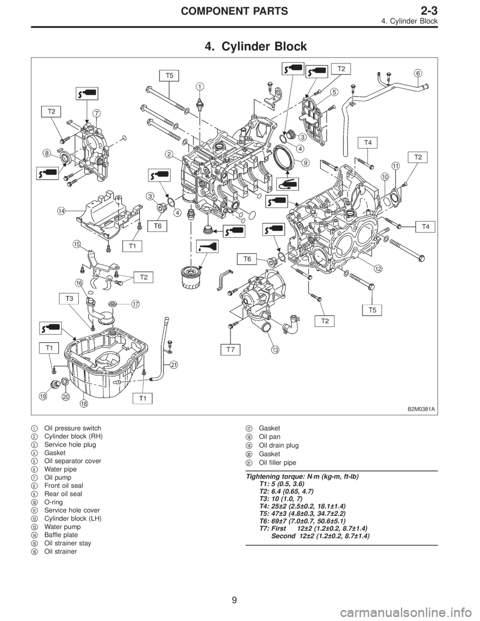
4. Cylinder Block
B2M0381A
�1Oil pressure switch
�
2Cylinder block (RH)
�
3Service hole plug
�
4Gasket
�
5Oil separator cover
�
6Water pipe
�
7Oil pump
�
8Front oil seal
�
9Rear oil seal
�
10O-ring
�
11Service hole cover
�
12Cylinder block (LH)
�
13Water pump
�
14Baffle plate
�
15Oil strainer stay
�
16Oil strainer�
17Gasket
�
18Oil pan
�
19Oil drain plug
�
20Gasket
�
21Oil filler pipe
Tightening torque: N⋅m (kg-m, ft-lb)
T1: 5 (0.5, 3.6)
T2: 6.4 (0.65, 4.7)
T3: 10 (1.0, 7)
T4: 25±2 (2.5±0.2, 18.1±1.4)
T5: 47±3 (4.8±0.3, 34.7±2.2)
T6: 69±7 (7.0±0.7, 50.6±5.1)
T7: First 12±2 (1.2±0.2, 8.7±1.4)
Second 12±2 (1.2±0.2, 8.7±1.4)
9
2-3COMPONENT PARTS
4. Cylinder Block
Page 98 of 2248
TROUBLE
Engine will not start.
Rough idle and engine stall
Low output, hesitation and poor acceleration
Surging
Engine does not return to idle.
Dieseling (Run-on)
After burning in exhaust system
Knocking
Excessive engine oil consumption
Excessive fuel consumption Starter does not turn.
Initial combustion does not occur.
Initial combustion occurs.
Engine stalls after initial combustion.
LUBRICATION SYSTEM
22 3 3�Incorrect oil pressure
2�Loosened oil pump attaching bolts and defective
gasket
2�Defective oil filter seal
2�Defective crankshaft oil seal
32�Defective rocker cover gasket
2�Loosened oil drain plug or defective gasket
2�Loosened oil pan fitting bolts or defective oil pan
COOLING SYSTEM
33221�Overheating
333�Over cooling
OTHERS
113 3�Malfunction of Evaporative Emission Control
System
21�Stuck or damaged throttle valve
322 2�Accelerator cable out of adjustment
77
2-3DIAGNOSTICS
1. Engine Trouble in General
Page 99 of 2248

2. Engine Noise
Valve lash adjusters may make clicking noise once engine
starts. It is normal if clicking noise ceases after a few min-
utes.
If clicking noise continues after a few minutes, check
engine oil level and add oil if necessary.
Then, do as follows to cease clicking noise.
1) Warm-up engine for five minutes.
2) Turn ignition switch OFF.
3) Connect test mode connector.
4) Start the engine and run it at approximately 2,000 rpm
for twenty minutes.
5) Turn ignition switch OFF.
6) Disconnect test mode connector.
7) Start the engine and check that clicking noise is ceased.
If noise still exists, conduct troubleshooting procedures in
accordance with the following table.
CAUTION:
Do not disconnect spark plug cord while engine is run-
ning.
Type of sound Condition Possible cause
Regular clicking soundSound increases as engine
speed increases.Valve mechanism is defective.
�Broken lash adjuster
�Worn valve rocker
�Worn camshaft
�Broken valve spring
�Worn valve lifter hole
Heavy and dull clankOil pressure is low.�Worn crankshaft main bearing
�Worn connecting rod bearing (big end)
Oil pressure is normal.�Loose flywheel mounting bolts
�Damaged engine mounting
High-pitched clank
(Spark knock)Sound is noticeable when
accelerating with an overload.�Ignition timing advanced
�Accumulation of carbon inside combustion chamber
�Wrong spark plug
�Improper gasoline
Clank when engine speed is
medium (1,000 to 2,000 rpm).Sound is reduced when fuel
injector connector of noisy
cylinder is disconnected.
(NOTE*)�Worn crankshaft main bearing
�Worn bearing at crankshaft end of connecting rod
Knocking sound when engine
is operating under idling speed
and engine is warm.Sound is reduced when fuel
injector connector of noisy
cylinder is disconnected.
(NOTE*)�Worn cylinder liner and piston ring
�Broken or stuck piston ring
�Worn piston pin and hole at piston end of connecting rod
Sound is not reduced if each
fuel injector connector is
disconnected in turn. (NOTE*)�Unusually worn valve lifter
�Worn cam gear
�Worn camshaft journal bore in crankcase
Squeaky sound—�Insufficient generator lubrication
Rubbing sound—�Defective generator brush and rotor contact
Gear scream when starting
engine—�Defective ignition starter switch
�Worn gear and starter pinion
Sound like polishing glass with
a dry cloth—�Loose drive belt
�Defective engine coolant pump shaft
78
2-3DIAGNOSTICS
2. Engine Noise
Page 101 of 2248

1. Lubrication System
A: SPECIFICATIONS
Lubrication methodForced lubrication
Oil pumpPump typeTrochoid type
Number of teethInner rotor 9
Outer rotor 10
Outer rotor diameter x thickness 78x9mm(3.07 x 0.35 in)
Tip clearance between inner and outer rotorSTANDARD 0.04 — 0.14 mm (0.0016 — 0.0055 in)
LIMIT 0.18 mm (0.0071 in)
Side clearance between inner rotor and pump
caseSTANDARD 0.02 — 0.07 mm (0.0008 — 0.0028 in)
LIMIT 0.15 mm (0.0059 in)
Case clearance between outer rotor and pump
caseSTANDARD 0.10 — 0.175 mm (0.0039 — 0.0069 in)
LIMIT 0.20 mm (0.0079 in)
Capacity at
80°C (176°F)700 rpm Discharge- pressure 98 kPa (1.0 kg/cm
2, 14 psi) or more
- quantity 4.2�(4.4 US qt, 3.7 Imp qt)/min.
5,000 rpm Discharge- pressure 294 kPa (3.0 kg/cm
2, 43 psi) or more
- quantity 42.0�(11.10 US gal, 9.24 Imp gal)/min.
Relief valve operation pressure 490 kPa (5.0 kg/cm
2, 71 psi)
Oil filterTypeFull-flow filter type
Filtration area 1,000 cm
2(155 sq in)
By-pass valve opening pressure 157 kPa (1.6 kg/cm
2, 23 psi)
Outer diameter x width 80 x 70 mm (3.15 x 2.76 in)
Oil filter to engine thread size M 20 x 1.5
Relief valve (on rocker shaft) operation pressure 69 kPa (0.7kg/cm
2, 10 psi)
Oil pressure
switchTypeImmersed contact point type
Working voltage — wattage 12 V — 3.4 W or less
Warning light activation pressure 14.7 kPa (0.15 kg/cm
2, 2.1 psi)
Proof pressure More than 981 kPa (10 kg/cm
2, 142 psi)
Oil pan capacity4.0�(4.2 US qt, 3.5 Imp qt)
2
2-4SPECIFICATIONS AND SERVICE DATA
1. Lubrication System
Page 102 of 2248
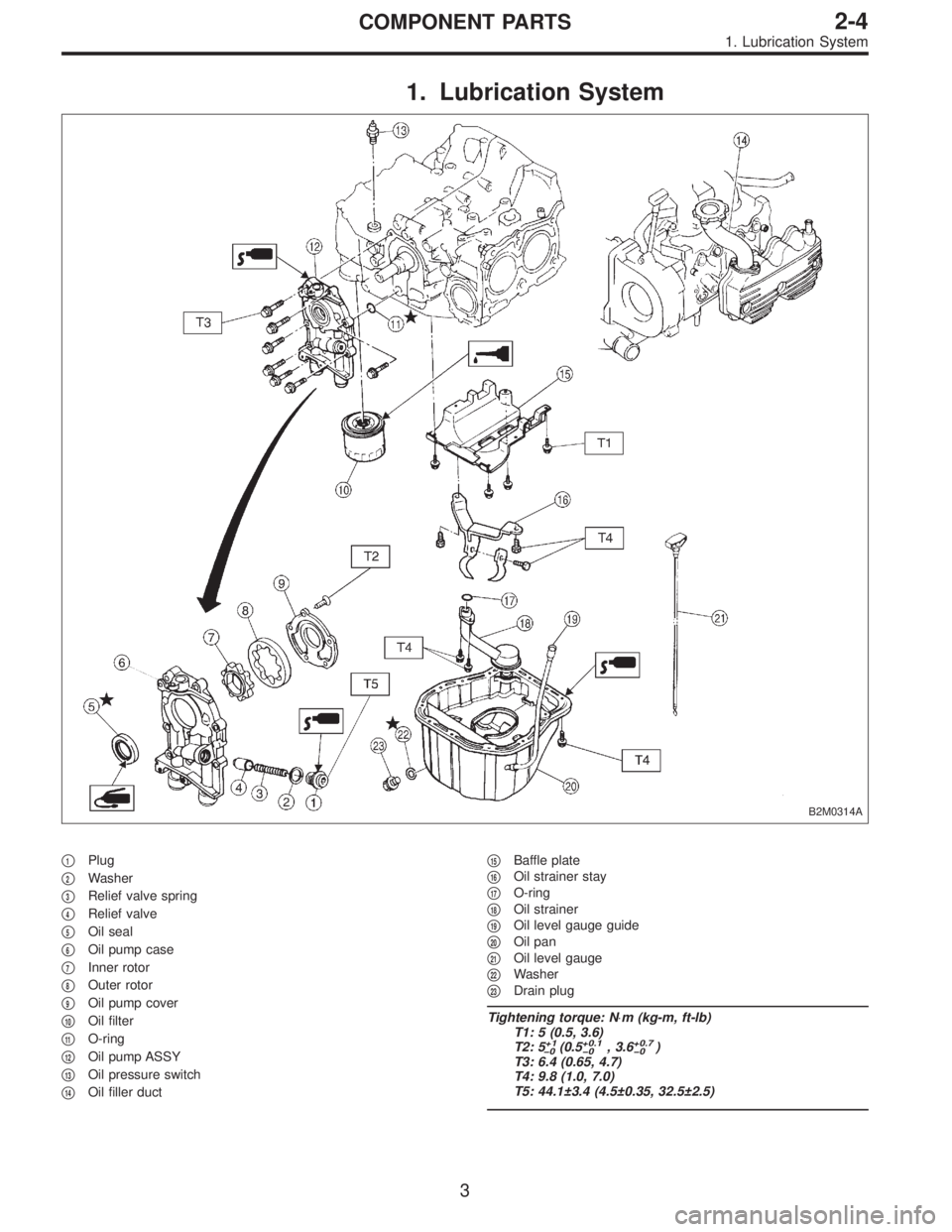
1. Lubrication System
B2M0314A
�1Plug
�
2Washer
�
3Relief valve spring
�
4Relief valve
�
5Oil seal
�
6Oil pump case
�
7Inner rotor
�
8Outer rotor
�
9Oil pump cover
�
10Oil filter
�
11O-ring
�
12Oil pump ASSY
�
13Oil pressure switch
�
14Oil filler duct�
15Baffle plate
�
16Oil strainer stay
�
17O-ring
�
18Oil strainer
�
19Oil level gauge guide
�
20Oil pan
�
21Oil level gauge
�
22Washer
�
23Drain plug
Tightening torque: N⋅m (kg-m, ft-lb)
T1: 5 (0.5, 3.6)
T2: 5
+1
�0(0.5+0.1
�0, 3.6+0.7
�0)
T3: 6.4 (0.65, 4.7)
T4: 9.8 (1.0, 7.0)
T5: 44.1±3.4 (4.5±0.35, 32.5±2.5)
3
2-4COMPONENT PARTS
1. Lubrication System
 Remove generator from bracket.
(1) Disconnect connector and terminal from generator.
G2M0089
(2) Remove V-belt cover.
(3) Loosen lock bolt and slider b")
 Connect oil pressure gauge hose to cylinder block.
5) Start the engine, and measure oil pressure.
Oil pressure:
98 kPa (1.0 kg/cm
2,14 psi) or more at 800 rpm
294 kPa (3.0 kg/cm2, 43 psi) o")


After burning in exhaust system
Knock")