Page 98 of 2248
TROUBLE
Engine will not start.
Rough idle and engine stall
Low output, hesitation and poor acceleration
Surging
Engine does not return to idle.
Dieseling (Run-on)
After burning in exhaust system
Knocking
Excessive engine oil consumption
Excessive fuel consumption Starter does not turn.
Initial combustion does not occur.
Initial combustion occurs.
Engine stalls after initial combustion.
LUBRICATION SYSTEM
22 3 3�Incorrect oil pressure
2�Loosened oil pump attaching bolts and defective
gasket
2�Defective oil filter seal
2�Defective crankshaft oil seal
32�Defective rocker cover gasket
2�Loosened oil drain plug or defective gasket
2�Loosened oil pan fitting bolts or defective oil pan
COOLING SYSTEM
33221�Overheating
333�Over cooling
OTHERS
113 3�Malfunction of Evaporative Emission Control
System
21�Stuck or damaged throttle valve
322 2�Accelerator cable out of adjustment
77
2-3DIAGNOSTICS
1. Engine Trouble in General
Page 126 of 2248

G2M0213
C: INSTALLATION
Installation is in the reverse order of removal.
CAUTION:
�Replace gasket with a new one.
�When installing engine coolant pump, tighten bolts
in two stages in numerical sequence as shown in fig-
ure.
Tightening torque:
10
+4
�0N⋅m (1.0+0.4
�0kg-m, 7.2+2.9
�0ft-lb)
G2M0214
3. Thermostat
A: REMOVAL AND INSTALLATION
1) Drain engine coolant.
Set container under the vehicle, and remove drain cock
from radiator.
2) Disconnect radiator outlet hose from thermostat cover.
3) Remove thermostat cover and gasket, and pull out the
thermostat.
G2M0227
4) Install the thermostat in the intake manifold, and install
the thermostat cover together with a gasket.
CAUTION:
�When reinstalling the thermostat, use a new gasket.
�The thermostat must be installed with the jiggle pin
upward.
�In this time, set the jiggle pin of thermostat for front
side.
G2M0215
B: INSPECTION
Replace the thermostat if the valve does not close com-
pletely at an ambient temperature or if the following test
shows unsatisfactory results.
Immerse the thermostat and a thermometer in water. Raise
water temperature gradually, and measure the temperature
and valve lift when the valve begins to open and when the
valve is fully opened. During the test, agitate the water for
even temperature distribution. The measurement should
be to the specification.
Starts to open:
76.0—80.0°C (169—176°F)
Fully opens:
91°C (196°F)
11
2-5SERVICE PROCEDURE
2. Engine Coolant Pump - 3. Thermostat
Page 127 of 2248

G2M0213
C: INSTALLATION
Installation is in the reverse order of removal.
CAUTION:
�Replace gasket with a new one.
�When installing engine coolant pump, tighten bolts
in two stages in numerical sequence as shown in fig-
ure.
Tightening torque:
10
+4
�0N⋅m (1.0+0.4
�0kg-m, 7.2+2.9
�0ft-lb)
G2M0214
3. Thermostat
A: REMOVAL AND INSTALLATION
1) Drain engine coolant.
Set container under the vehicle, and remove drain cock
from radiator.
2) Disconnect radiator outlet hose from thermostat cover.
3) Remove thermostat cover and gasket, and pull out the
thermostat.
G2M0227
4) Install the thermostat in the intake manifold, and install
the thermostat cover together with a gasket.
CAUTION:
�When reinstalling the thermostat, use a new gasket.
�The thermostat must be installed with the jiggle pin
upward.
�In this time, set the jiggle pin of thermostat for front
side.
G2M0215
B: INSPECTION
Replace the thermostat if the valve does not close com-
pletely at an ambient temperature or if the following test
shows unsatisfactory results.
Immerse the thermostat and a thermometer in water. Raise
water temperature gradually, and measure the temperature
and valve lift when the valve begins to open and when the
valve is fully opened. During the test, agitate the water for
even temperature distribution. The measurement should
be to the specification.
Starts to open:
76.0—80.0°C (169—176°F)
Fully opens:
91°C (196°F)
11
2-5SERVICE PROCEDURE
2. Engine Coolant Pump - 3. Thermostat
Page 194 of 2248
G2M0345
3. Fuel Tank
A: REMOVAL
1) Release fuel pressure.
2) Drain fuel from fuel tank.
G2M0382
3) Remove rear exhaust pipe.
(1) Lift-up the vehicle.
(2) Separate rear exhaust pipe from center exhaust
pipe.
(3) Separate rear exhaust pipe from muffler.
(4) Remove bracket from rubber cushion, and remove
exhaust pipe.
NOTE:
To facilitate the removal of parts, apply a coat of SUBARU
CRC5-56 (Part No. 004301003)
G2M0384
4) Remove muffler assembly.
NOTE:
To facilitate the removal of parts, apply a coat of SUBARU
CRC5-56 (Part No. 004301003)
G3M0059
5) Remove rear differential assembly. (AWD model)
(1) Remove rear axle shafts from rear differential
assembly.
(2) Remove rear differential front cover.
(3) Remove propeller shaft.
(4) Remove lower differential bracket.
(5) Set transmission jack under rear differential.
(6) Remove bolts which install rear differential onto
rear crossmember.
9
2-8SERVICE PROCEDURE
3. Fuel Tank
Page 240 of 2248

2. Engine
A: REMOVAL
1. Set the vehicle on lift arms.
2. Open front hood and support with a stay.
3. Release fuel pressure.
4. Disconnect battery cable and remove battery from vehicle.
5. Drain coolant.
6. Remove cooling system.
With A/C
7. Collect refrigerant, and remove pressure hoses.
8. Remove air intake system.
9. Remove canister and bracket.
10. Disconnect connectors, cables and hoses.
11. Remove power steering pump from bracket.
12. Remove front exhaust pipe and center exhaust pipe.
13. Remove nuts which hold lower side of transmission to
engine.
14. Remove nuts which install front cushion rubber onto front
crossmember.
AT model
15. Separate torque converter from drive plate.
16. Remove pitching stopper.
17. Disconnect fuel delivery hose, return hose and evaporation
hoses.
18. Support engine with a lifting device and wire ropes.
19. Support transmission with a garage jack.
20. Remove bolts which hold upper side of transmission to
engine.
21. Remove engine from vehicle.
�
�
�
�
�
�
�
�
�
�
�
�
�
�
�
6
2-11SERVICE PROCEDURE
2. Engine
Page 259 of 2248
3. Transmission
A: REMOVAL
1. Open front hood fully, and support it with stay.
2. Disconnect battery ground terminal.
3. Remove air intake duct.
4. Disconnect connectors and cables.
5. Remove starter.
6. Remove pitching stopper.
AT model
7. Separate torque converter from drive plate.
8. Remove ATF level gauge.
9. Remove transmission connector bracket.
10. Set special tools.
11. Remove bolt which holds right upper side of transmission to
engine.
12. Remove exhaust system.
�Front exhaust pipe
�Center exhaust pipe
�Rear exhaust pipe [AWD]
AT model
13. Drain ATF to remove ATF drain plug.
14. Disconnect ATF cooler hose from pipe on transmission side,
and remove ATF level gauge guide.
AWD model
15. Remove propeller shaft.
�A
�
�
�
�
�
�
�
�
�
�
�
�
25
2-11SERVICE PROCEDURE
3. Transmission
Page 265 of 2248
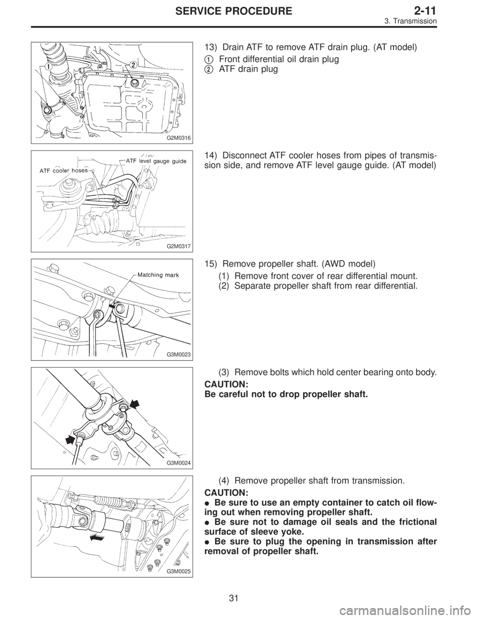
G2M0316
13) Drain ATF to remove ATF drain plug. (AT model)
�
1Front differential oil drain plug
�
2ATF drain plug
G2M0317
14) Disconnect ATF cooler hoses from pipes of transmis-
sion side, and remove ATF level gauge guide. (AT model)
G3M0023
15) Remove propeller shaft. (AWD model)
(1) Remove front cover of rear differential mount.
(2) Separate propeller shaft from rear differential.
G3M0024
(3) Remove bolts which hold center bearing onto body.
CAUTION:
Be careful not to drop propeller shaft.
G3M0025
(4) Remove propeller shaft from transmission.
CAUTION:
�Be sure to use an empty container to catch oil flow-
ing out when removing propeller shaft.
�Be sure not to damage oil seals and the frictional
surface of sleeve yoke.
�Be sure to plug the opening in transmission after
removal of propeller shaft.
31
2-11SERVICE PROCEDURE
3. Transmission
Page 283 of 2248
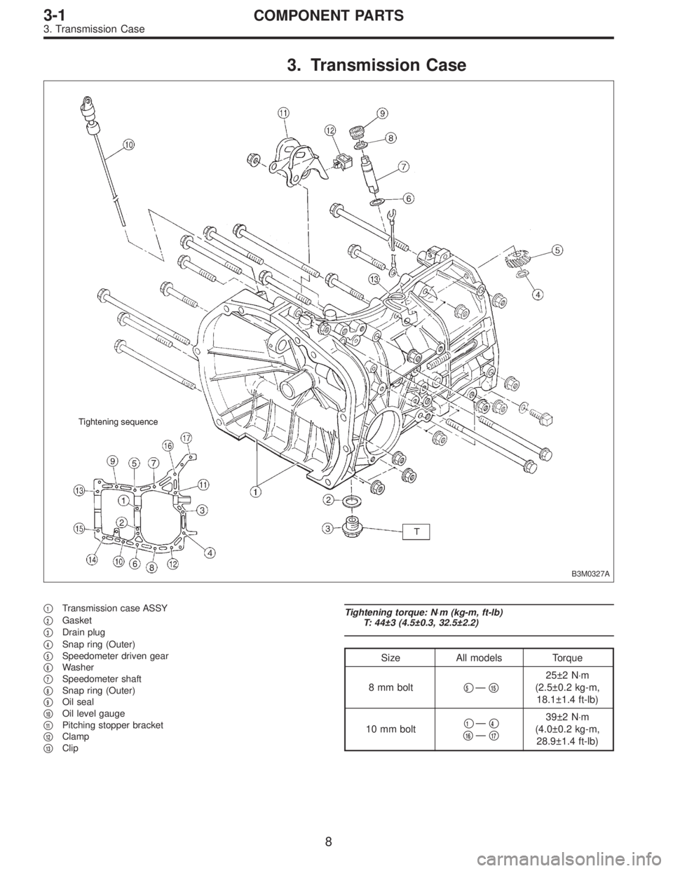
3. Transmission Case
B3M0327A
�1Transmission case ASSY
�
2Gasket
�
3Drain plug
�
4Snap ring (Outer)
�
5Speedometer driven gear
�
6Washer
�
7Speedometer shaft
�
8Snap ring (Outer)
�
9Oil seal
�
10Oil level gauge
�
11Pitching stopper bracket
�
12Clamp
�
13Clip
Tightening torque: N⋅m (kg-m, ft-lb)
T: 44±3 (4.5±0.3, 32.5±2.2)
Size All models Torque
8 mm bolt�
5—�15
25±2 N⋅m
(2.5±0.2 kg-m,
18.1±1.4 ft-lb)
10 mm bolt�
1—�4
�16—�17
39±2 N⋅m
(4.0±0.2 kg-m,
28.9±1.4 ft-lb)
8
3-1COMPONENT PARTS
3. Transmission Case

After burning in exhaust system
Knock")
![SUBARU LEGACY 1995 Service Repair Manual G2M0345
3. Fuel Tank
A: REMOVAL
1) Release fuel pressure. <Ref. to 2-8 [W1A0].>
2) Drain fuel from fuel tank. <Ref. to 2-8 [W1B0].>
G2M0382
3) Remove rear exhaust pipe.
(1) Lift-up the vehicle.
(2) Se](/manual-img/17/57432/w960_57432-193.png "SUBARU LEGACY 1995 Service Repair Manual G2M0345
3. Fuel Tank
A: REMOVAL
1) Release fuel pressure. <Ref. to 2-8 [W1A0].>
2) Drain fuel from fuel tank. <Ref. to 2-8 [W1B0].>
G2M0382
3) Remove rear exhaust pipe.
(1) Lift-up the vehicle.
(2) Se")