Page 606 of 2248
5. Replacement of Front DOJ and UFJ
Boots
A: REMOVAL
1) Disconnect ground cable from battery.
2) Jack-up vehicle, support it with safety stands (rigid
rocks), and remove front wheel cap and wheels.
NOTE:
Do not remove axle nut.
3) Remove stabilizer link.
4) Disconnect transverse link from housing.
G4M0279
5) Remove spring pin which secures transmission spindle
to DOJ.
CAUTION:
Use a new spring pin.
6) Remove DOJ and UFJ boot from drive shaft.
B: INSTALLATION
1) Install DOJ and UFJ boots to drive shaft.
G4M0279
2) Install DOJ on transmission spindle and drive spring pin
into place.
CAUTION:
Always use a new spring pin.
3) Connect transverse link to housing.
4) Install stabilizer link.
41
4-2SERVICE PROCEDURE
5. Replacement of Front DOJ and UFJ Boots
Page 607 of 2248
6. Replacement of Rear DOJ and BJ
Boots
A: REMOVAL
1) Disconnect ground cable from battery.
2) Lift-up vehicle, and remove rear wheel cap and wheels.
NOTE:
Axle nut need not be removed.
3) Remove A.B.S. sensor clamps and parking brake cable
bracket.
4) Disconnect stabilizer link from lateral link.
5) Remove bolts which secure lateral link assembly to rear
housing.
6) Remove bolts which secure trailing link assembly to
rear housing.
7) Remove crossmember reinforcement lower from cross-
member (4 door model only).
G4M0994
8) Remove DOJ from rear differential using ST.
ST 28099PA100 DRIVE SHAFT REMOVER
NOTE:
The side spline shaft circlip comes out together with the
shaft.
G4M0995
CAUTION:
Be careful not to damage side bearing retainer. Always
use bolt as shown in figure, as supporting point for ST
during removal.
ST 28099PA100 DRIVE SHAFT REMOVER
B: INSTALLATION
1) Install DOJ and BJ boots to drive shaft.
42
4-2SERVICE PROCEDURE
6. Replacement of Rear DOJ and BJ Boots
Page 1102 of 2248
![SUBARU LEGACY 1995 Service Repair Manual CAUTION:
�Observe the items in 1. NORMAL CHARGING
[W2C1].
�Never use more than 10 amperes when charging the
battery because that will shorten battery life.
3. JUDGMENT OF BATTERY IN CHARGED
CONDITION](/manual-img/17/57432/w960_57432-1101.png "SUBARU LEGACY 1995 Service Repair Manual CAUTION:
�Observe the items in 1. NORMAL CHARGING
[W2C1].
�Never use more than 10 amperes when charging the
battery because that will shorten battery life.
3. JUDGMENT OF BATTERY IN CHARGED
CONDITION")
CAUTION:
�Observe the items in 1. NORMAL CHARGING
[W2C1].
�Never use more than 10 amperes when charging the
battery because that will shorten battery life.
3. JUDGMENT OF BATTERY IN CHARGED
CONDITION
1) Specific gravity of electrolyte is held at a specific value
in a range from 1.250 to 1.290 for more than one hour.
2) Voltage per battery cell is held at a specific value in a
range from 2.5 to 2.8 volts for more than one hour.
4. CHECK HYDROMETER FOR STATE OF CHARGE
Hydrometer indicator State of charge Required action
Green dot Above 65% Load test
Dark dot Below 65% Charge battery
Clear dot Low electrolyteReplace battery.* (If
cranking complaint)
*: Check electrical system before replacement.
B6M0236
3. Ignition Switch
A: REMOVAL AND INSTALLATION
1. IGNITION SWITCH
1) Remove screws, separate upper column cover and
lower column cover.
2) Remove instrument panel lower cover.
B6M0333
3) Disconnect ignition switch connector from body har-
ness.
4) Using a drift and hammer, hit the torn bolt head to
loosen and remove the ignition switch.
B6M0334A
5) When installing, tighten the connecting bolt until its
head twists off.
7
6-2SERVICE PROCEDURE
2. Battery - 3. Ignition Switch
Page 1103 of 2248
![SUBARU LEGACY 1995 Service Repair Manual CAUTION:
�Observe the items in 1. NORMAL CHARGING
[W2C1].
�Never use more than 10 amperes when charging the
battery because that will shorten battery life.
3. JUDGMENT OF BATTERY IN CHARGED
CONDITION](/manual-img/17/57432/w960_57432-1102.png "SUBARU LEGACY 1995 Service Repair Manual CAUTION:
�Observe the items in 1. NORMAL CHARGING
[W2C1].
�Never use more than 10 amperes when charging the
battery because that will shorten battery life.
3. JUDGMENT OF BATTERY IN CHARGED
CONDITION")
CAUTION:
�Observe the items in 1. NORMAL CHARGING
[W2C1].
�Never use more than 10 amperes when charging the
battery because that will shorten battery life.
3. JUDGMENT OF BATTERY IN CHARGED
CONDITION
1) Specific gravity of electrolyte is held at a specific value
in a range from 1.250 to 1.290 for more than one hour.
2) Voltage per battery cell is held at a specific value in a
range from 2.5 to 2.8 volts for more than one hour.
4. CHECK HYDROMETER FOR STATE OF CHARGE
Hydrometer indicator State of charge Required action
Green dot Above 65% Load test
Dark dot Below 65% Charge battery
Clear dot Low electrolyteReplace battery.* (If
cranking complaint)
*: Check electrical system before replacement.
B6M0236
3. Ignition Switch
A: REMOVAL AND INSTALLATION
1. IGNITION SWITCH
1) Remove screws, separate upper column cover and
lower column cover.
2) Remove instrument panel lower cover.
B6M0333
3) Disconnect ignition switch connector from body har-
ness.
4) Using a drift and hammer, hit the torn bolt head to
loosen and remove the ignition switch.
B6M0334A
5) When installing, tighten the connecting bolt until its
head twists off.
7
6-2SERVICE PROCEDURE
2. Battery - 3. Ignition Switch
Page 1314 of 2248
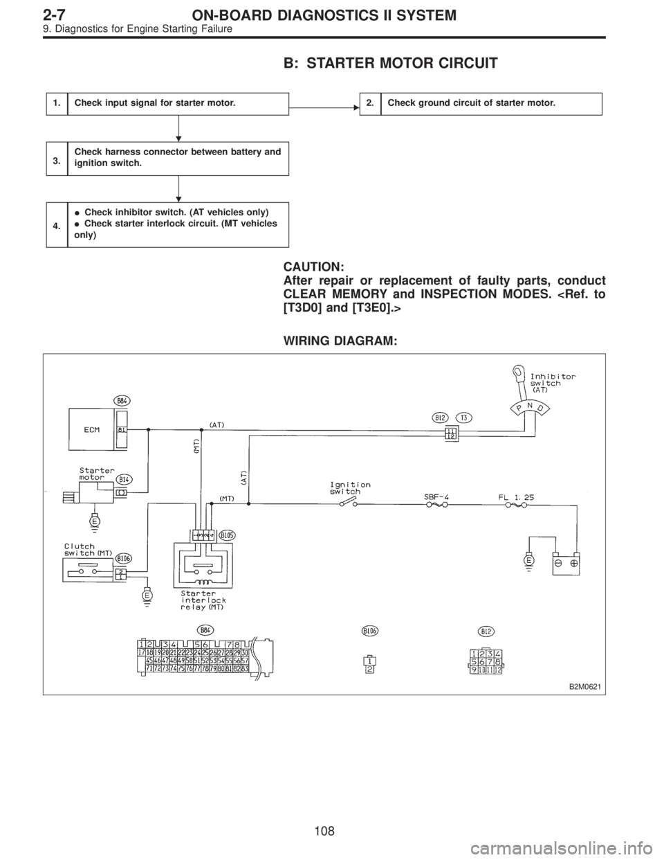
B: STARTER MOTOR CIRCUIT
1.Check input signal for starter motor.�2.Check ground circuit of starter motor.
3.Check harness connector between battery and
ignition switch.
4.
�Check inhibitor switch. (AT vehicles only)
�Check starter interlock circuit. (MT vehicles
only)
CAUTION:
After repair or replacement of faulty parts, conduct
CLEAR MEMORY and INSPECTION MODES.
[T3D0] and [T3E0].>
WIRING DIAGRAM:
B2M0621
�
�
108
2-7ON-BOARD DIAGNOSTICS II SYSTEM
9. Diagnostics for Engine Starting Failure
 Disconnect ground cable from battery.
2) Jack-up vehicle, support it with safety stands (rigid
rocks), and remove front wheel cap and wheels.
NO")
 Disconnect ground cable from battery.
2) Lift-up vehicle, and remove rear wheel cap and wheels.
NOTE:
Axle nut need not be removed.
3) Remove A.B.")