Page 36 of 2248
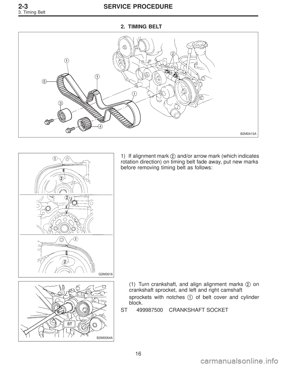
2. TIMING BELT
B2M0415A
G2M0616
1) If alignment mark�2and/or arrow mark (which indicates
rotation direction) on timing belt fade away, put new marks
before removing timing belt as follows:
B2M0064A
(1) Turn crankshaft, and align alignment marks�2on
crankshaft sprocket, and left and right camshaft
sprockets with notches�
1of belt cover and cylinder
block.
ST 499987500 CRANKSHAFT SOCKET
16
2-3SERVICE PROCEDURE
3. Timing Belt
Page 37 of 2248
G2M0111
(2) Using white paint, put alignment and/or arrow
marks on timing belts in relation to the sprockets.
Z
1: 44 tooth length
Z
2: 40.5 tooth length
B2M0065
2) Loosen tensioner adjuster mounting bolts.
3) Remove belt idler.
4) Remove belt idler No. 2.
5) Remove timing belt.
6) Remove tensioner adjuster.
17
2-3SERVICE PROCEDURE
3. Timing Belt
Page 45 of 2248
G2M0122
1) Installation of timing belt
(1) Using ST, turn left and right camshaft sprockets so
that their alignment marks come to top positions.
ST 499207100 CAMSHAFT SPROCKET WRENCH
B2M0417A
(2) While aligning alignment mark on timing belt with
marks on sprockets, position timing belt properly.
CAUTION:
Ensure belt’s rotating direction is correct.
2) Install belt idler No. 2.
3) Install belt idler.
B2M0111
4) Loosen belt tension adjuster attaching bolts and move
adjuster all the way to the left. Tighten the bolts.
G2M0125
5) After ensuring that the marks on timing belt and cam-
shaft sprockets are aligned, remove stopper pin from belt
tension adjuster.
CAUTION:
After properly installing timing belt, remove rocker
cover and ensure that the valve lash adjuster contains
no air.
25
2-3SERVICE PROCEDURE
3. Timing Belt
Page 104 of 2248
 Remove oil pump by using flat-bladed screwdriver.
CAUTION:
Be careful not to scratch mating surfaces of cylinder
block and oil pump.
B2M0315A
B: DISASSEMBLY
Remove screws which secure oil p")
G2M0071
7) Remove oil pump by using flat-bladed screwdriver.
CAUTION:
Be careful not to scratch mating surfaces of cylinder
block and oil pump.
B2M0315A
B: DISASSEMBLY
Remove screws which secure oil pump cover and disas-
semble oil pump.
Inscribe alignment marks on inner and outer rotors so that
they can be replaced in their original positions during reas-
sembly.
CAUTION:
Before removing relief valve, loosen plug when remov-
ing oil pump from cylinder block.
�
1Oil seal
�
2Pump case
�
3Inner rotor
�
4Outer rotor
�
5Pump cover
�
6Relief valve
�
7Relief spring
�
8Plug
�
9Washer
�
10O-ring
B2M0316A
C: INSPECTION
1. TIP CLEARANCE
Measure the tip clearance of rotors. If the clearance
exceeds the limit, replace rotors as a matched set.
Tip clearance:
Standard
0.04—0.14 mm (0.0016—0.0055 in)
Limit
0.18 mm (0.0071 in)
B2M0317A
2. CASE CLEARANCE
Measure the clearance between the outer rotor and the
cylinder block rotor housing. If the clearance exceeds the
limit, replace the rotor.
Case clearance:
Standard
0.10—0.175 mm (0.0039—0.0069 in)
Limit
0.20 mm (0.0079 in)
5
2-4SERVICE PROCEDURE
1. Oil Pump
Page 316 of 2248
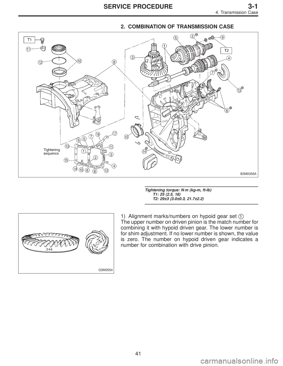
2. COMBINATION OF TRANSMISSION CASE
B3M0356A
Tightening torque: N⋅m (kg-m, ft-lb)
T1: 25 (2.5, 18)
T2: 29±3 (3.0±0.3, 21.7±2.2)
G3M0554
1) Alignment marks/numbers on hypoid gear set�1
The upper number on driven pinion is the match number for
combining it with hypoid driven gear. The lower number is
for shim adjustment. If no lower number is shown, the value
is zero. The number on hypoid driven gear indicates a
number for combination with drive pinion.
41
3-1SERVICE PROCEDURE
4. Transmission Case
Page 517 of 2248

Symptom and possible cause Remedy
5. Noises when cornering
�
1Damaged differential gear. Replace.
�
2Excessive wear or damage of thrust washer. Replace.
�
3Broken pinion mate shaft. Replace.
�
4Seized or damaged side bearing. Replace.
6. Gear noises
Since noises from engine, muffler, transmission, propeller shaft, wheel bearings, tires, and body are sometimes mistaken for noises
from differential assembly, be careful in checking them. Inspection methods to locate noises include coasting, accelerating, cruising,
and jacking-up all four wheels. Perform these inspections according to condition of trouble. When listening to noises, shift gears into
four wheel drive and fourth speed position, trying to pick up only differential noise.
�
1Improper tooth contact of hypoid gear. Readjust or replace hypoid gear set.
�
2Improper backlash for hypoid gear. Readjust.
�
3Scored or chipped teeth of hypoid gear. Replace hypoid gear set.
�
4Seized hypoid gear. Replace hypoid gear set.
�
5Improper preload for front or rear bearings. Readjust.
�
6Seized, scored, or chipped front or rear bearing. Replace.
�
7Seized, scored, or chipped side bearing. Replace.
�
8Vibrating differential carrier. Replace.
2. Propeller Shaft
Symptom and possible cause Remedy
1. Vibration of propeller shaft
Vibration is caused by propeller shaft during operation and is transferred to vehicle body. Generally vibration increase in proportion to
vehicle speed.
�
1Worn or damaged universal joint. Replace.
�
2Unbalanced propeller shaft due to bend or dent. Replace.
�
3Loose installation of propeller shaft. Retighten.
�
4Worn or damaged center bearing and damaged center mount-
ing rubber.Replace.
2. Tapping when starting and noise while cruising, caused by propeller shaft.
�
1Worn or damaged universal joint. Replace.
�
2Worn spline of sleeve yoke. Replace.
�
3Loose installation of propeller shaft. Retighten.
�
4Loose installation of joint. Replace.
�
5Worn or damaged center bearing and damaged center mount-
ing rubber.Replace.
NOTE:
Vibration while cruising may be caused by an unbalanced
tire, improper tire inflation pressure, improper wheel
alignment, etc.
41
3-4DIAGNOSTICS
1. Rear Differential - 2. Propeller Shaft
Page 518 of 2248

Symptom and possible cause Remedy
5. Noises when cornering
�
1Damaged differential gear. Replace.
�
2Excessive wear or damage of thrust washer. Replace.
�
3Broken pinion mate shaft. Replace.
�
4Seized or damaged side bearing. Replace.
6. Gear noises
Since noises from engine, muffler, transmission, propeller shaft, wheel bearings, tires, and body are sometimes mistaken for noises
from differential assembly, be careful in checking them. Inspection methods to locate noises include coasting, accelerating, cruising,
and jacking-up all four wheels. Perform these inspections according to condition of trouble. When listening to noises, shift gears into
four wheel drive and fourth speed position, trying to pick up only differential noise.
�
1Improper tooth contact of hypoid gear. Readjust or replace hypoid gear set.
�
2Improper backlash for hypoid gear. Readjust.
�
3Scored or chipped teeth of hypoid gear. Replace hypoid gear set.
�
4Seized hypoid gear. Replace hypoid gear set.
�
5Improper preload for front or rear bearings. Readjust.
�
6Seized, scored, or chipped front or rear bearing. Replace.
�
7Seized, scored, or chipped side bearing. Replace.
�
8Vibrating differential carrier. Replace.
2. Propeller Shaft
Symptom and possible cause Remedy
1. Vibration of propeller shaft
Vibration is caused by propeller shaft during operation and is transferred to vehicle body. Generally vibration increase in proportion to
vehicle speed.
�
1Worn or damaged universal joint. Replace.
�
2Unbalanced propeller shaft due to bend or dent. Replace.
�
3Loose installation of propeller shaft. Retighten.
�
4Worn or damaged center bearing and damaged center mount-
ing rubber.Replace.
2. Tapping when starting and noise while cruising, caused by propeller shaft.
�
1Worn or damaged universal joint. Replace.
�
2Worn spline of sleeve yoke. Replace.
�
3Loose installation of propeller shaft. Retighten.
�
4Loose installation of joint. Replace.
�
5Worn or damaged center bearing and damaged center mount-
ing rubber.Replace.
NOTE:
Vibration while cruising may be caused by an unbalanced
tire, improper tire inflation pressure, improper wheel
alignment, etc.
41
3-4DIAGNOSTICS
1. Rear Differential - 2. Propeller Shaft
Page 519 of 2248

Front Rear
Sedan 19 (0.75) 15 (0.59)
Wagon 19 (0.75) 15 (0.59)
B: WHEEL ALIGNMENT
Sedan Wagon
FWD AWD FWD AWD
FrontCamber
(tolerance: ±0")
1. Suspension
A: SPECIFICATIONS
1. STABILIZER
Bar dia. mm (in)
Front Rear
Sedan 19 (0.75) 15 (0.59)
Wagon 19 (0.75) 15 (0.59)
B: WHEEL ALIGNMENT
Sedan Wagon
FWD AWD FWD AWD
FrontCamber
(tolerance: ±0°30′)�0°05′�0°05′�0°05′�0°05′
Caster
(tolerance: ±1°)3°05′3°05′3°05′3°05′
Toe-in mm (in) 0±3 (0±0.12) Total toe angle: 0°±20′
Kingpin angle (tolerance: ±1°) 14°15′14°15′14°15′14°15′
Wheel arch height
[tolerance:
+12
�24mm (+0.47
� 0.94in)] mm (in)385 (15.16) 385 (15.16) 385 (15.16) 385 (15.16)
RearCamber
(tolerance: ±0°45′)�0°55′�1° �0°45′�0°55′
Toe-in mm (in) 0±3 (0±0.12) Total toe angle: 0°±20′
Wheel arch height
[tolerance:
+12
�24mm (+0.47
� 0.94in)] mm (in)369 (14.53) 369 (14.53) 379 (14.92) 379 (14.92)
Thrust angle 0°±20′
B4M0182A
NOTE:
�Front and rear toe-ins and front camber can be adjusted.
If toe-in or front camber tolerance exceeds specifications,
adjust toe-in and camber to the specification.
�The other items indicated in the specification table can-
not be adjusted. If the other items exceeds specifications,
check suspension parts and joint portions of body suspen-
sion parts for deformities; and replace with new ones as
required.
2
4-1SPECIFICATIONS AND SERVICE DATA
1. Suspension
 Using white paint, put alignment and/or arrow
marks on timing belts in relation to the sprockets.
Z
1: 44 tooth length
Z
2: 40.5 tooth length
B2M0065
2) Loosen tensioner adjuster mounting")
 Installation of timing belt
(1) Using ST, turn left and right camshaft sprockets so
that their alignment marks come to top positions.
ST 499207100 CAMSHAFT SPROCKET WRENCH
B2M0417A
(2) Whil")