Page 239 of 2248
1. General Precaution
1) Remove or install engine and transmission in an area
where chain hoists, lifting devices, etc. are available for
ready use.
2) Be sure not to damage coated surfaces of body panels
with tools or stain seats and windows with coolant or oil.
Place a cover over fenders, as required, for protection.
3) Prior to starting work, prepare the following:
Service tools, clean cloth, containers to catch coolant and
oil, wire ropes, chain hoist, transmission jacks, etc.
4) Lift-up or lower the vehicle when necessary. Make sure
to support the correct positions. (Refer to Chapter 1-3
“General Information”.)
5
2-11SERVICE PROCEDURE
1. General Precaution
Page 455 of 2248
G3M0489
2) Install the washer and differential bevel gear to the dif-
ferential case (LH). Then put the case over the differential
case (RH), and connect both cases.
3) Install the crown gear and secure by tightening the bolt.
Standard tightening torque:
62±5 N⋅m (6.3±0.5 kg-m, 45.6±3.6 ft-lb)
G3M0491
4) Measurement of backlash (Selection of washer)
Measure the gear backlash with ST1 and ST2, and insert
ST2 through the access window of the case.
ST1 498247001 MAGNET BASE
ST2 498247100 DIAL GAUGE
Standard value:
0.13—0.18 mm (0.0051—0.0071 in)
NOTE:
Measure the backlash by applying a pinion tooth between
two bevel gear teeth.
G3M0492
5) Install the speedometer drive gear. Then force-fit the
taper roller bearing with a press and ST.
ST 398487700 DRIFT
CAUTION:
Be sure to position correctly the locking end of the
speedometer drive gear.
108
3-2SERVICE PROCEDURE
14. Differential Case Assembly
Page 881 of 2248

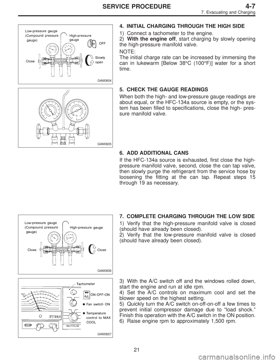
G4M0604
4. INITIAL CHARGING THROUGH THE HIGH SIDE
1) Connect a tachometer to the engine.
2)With the engine off, start charging by slowly opening
the high-pressure manifold valve.
NOTE:
The initial charge rate can be increased by immersing the
can in lukewarm [Below 38°C (100°F)] water for a short
time.
G4M0605
5. CHECK THE GAUGE READINGS
When both the high- and low-pressure gauge readings are
about equal, or the HFC-134a source is empty, or the sys-
tem has been filled to specifications, close the high- pres-
sure manifold valve.
6. ADD ADDITIONAL CANS
If the HFC-134a source is exhausted, first close the high-
pressure manifold valve, second, close the can tap valve,
then slowly purge the refrigerant from the service hose by
loosening the fitting at the can tap. Repeat steps 15
through 19 as necessary.
G4M0606
7. COMPLETE CHARGING THROUGH THE LOW SIDE
1) Verify that the high-pressure manifold valve is closed
(should have already been closed).
2) Verify that the low-pressure manifold valve is closed
(should have already been closed).
G4M0607
3) With the A/C switch off and the windows rolled down,
start the engine and run at idle rpm.
4) Set the A/C controls on maximum cool and set the
blower speed on the highest setting.
5) Quickly turn the A/C switch on-off-on-off a few times to
prevent initial compressor damage due to“load shock.”
Finish this operation with the A/C switch in the ON position.
6) Raise engine rpm to approximately 1,500 rpm.
21
4-7SERVICE PROCEDURE
7. Evacuating and Charging
Page 889 of 2248

10. Performance Test
1. VEHICLE SET UP
In order to obtain meaningful test results, the vehicle must
be set up to meet the following conditions:
1) Vehicle in shade
2) No wind
3) All vehicle doors closed
4) Front windows opened
5) Hood opened
6) Engine speed set at 1,500 rpm.
7) A/C ON
8) Temperature control lever—Maximum cold
9) Air source—Recirculation
10) Blower speed—4th position (High)
11) Operate A/C for 10 minutes (Minimum) before taking
measurement.
2. MEASUREMENTS
After 10 minutes (Minimum) of A/C operation and using
accurate test equipment, take the following measurements
(in order):
1) Evaporator intake air temperature at recirculation door.
2) Evaporator discharge air temperature at center grill.
3) Condenser (Ambient) intake air temperature measured
0.9 m (3 ft) in front and in line with the center of the con-
denser.
4) Suction (Low) side pressure
5) Discharge (High) side pressure
NOTE:
If only one thermometer is available; 1) take the ambient
measurement first; then 2) the intake air; and 3) dis-
charge air temperature.
29
4-7SERVICE PROCEDURE
10. Performance Test
Page 916 of 2248

9. Sight Glass Inspection
1. INSPECTION CONDITION
1) Operate the engine at approximately 1,500 rpm.
2) Open the door windows.
3) Set the fan switch to the 4th (High) position.
4) Set the mode selector switch to“A/C”position.
5) Set the temperature control switch to Full cold position.
6) Ensure that compressor discharge pressure is at least
588 kPa (6 kg/cm
2, 85 psi).
NOTE:
When discharge pressure does not reach 588 kPa (6
kg/cm
2, 85 psi) in areas where outside air temperature is
low, proceed as follows:
a. Set the TEMP. SWITCH to the Full hot position.
b. Set the temperature control switch to“MAX. A/C”posi-
tion.
c. Close the door windows completely.
d. Increase the compartment temperature so that dis-
charge pressure reaches at least 588 kPa (6 kg/cm
2,85
psi).
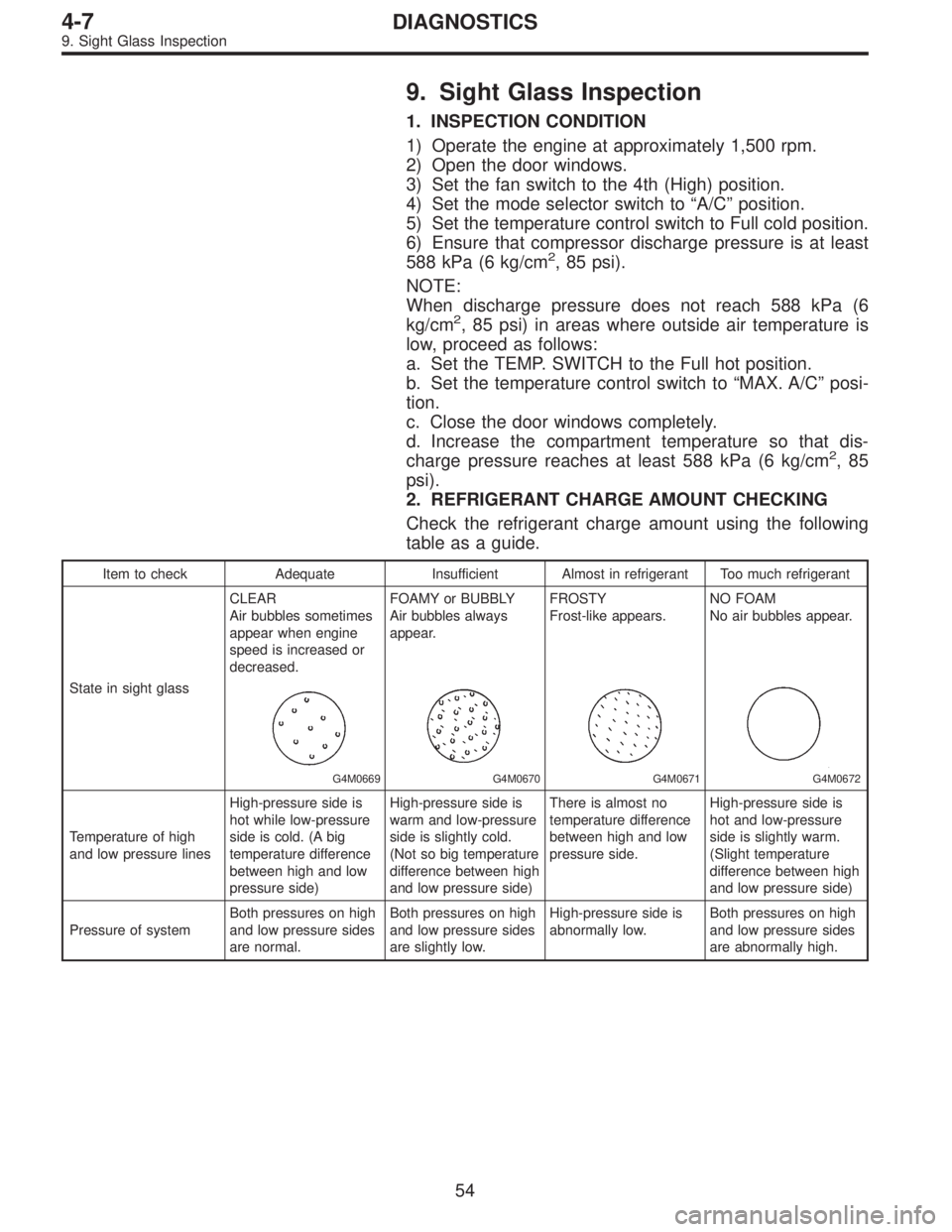
2. REFRIGERANT CHARGE AMOUNT CHECKING
Check the refrigerant charge amount using the following
table as a guide.
Item to check Adequate Insufficient Almost in refrigerant Too much refrigerant
State in sight glassCLEAR
Air bubbles sometimes
appear when engine
speed is increased or
decreased.
G4M0669
FOAMY or BUBBLY
Air bubbles always
appear.
G4M0670
FROSTY
Frost-like appears.
G4M0671
NO FOAM
No air bubbles appear.
G4M0672
Temperature of high
and low pressure linesHigh-pressure side is
hot while low-pressure
side is cold. (A big
temperature difference
between high and low
pressure side)High-pressure side is
warm and low-pressure
side is slightly cold.
(Not so big temperature
difference between high
and low pressure side)There is almost no
temperature difference
between high and low
pressure side.High-pressure side is
hot and low-pressure
side is slightly warm.
(Slight temperature
difference between high
and low pressure side)
Pressure of systemBoth pressures on high
and low pressure sides
are normal.Both pressures on high
and low pressure sides
are slightly low.High-pressure side is
abnormally low.Both pressures on high
and low pressure sides
are abnormally high.
54
4-7DIAGNOSTICS
9. Sight Glass Inspection
Page 935 of 2248
3. FRONT WINDSHIELD AND REAR WINDOW
B5M0254A
Unit: mm (in)
18
5-1SERVICE DATA
3. Datum Dimensions
Page 980 of 2248
3. Front Door Glass
B5M0054A
�1Glass
�
2Regulator and motor ASSY
�
3Regulator handle (Except power window)
�
4Retainer spring
�
5Regulator ASSY
Tightening torque: N⋅m (kg-m, ft-lb)
T: 7.4±2.0 (0.75±0.2, 5.4±1.4)
5
5-2COMPONENT PARTS
3. Front Door Glass
Page 981 of 2248
4. Rear Door Glass
B5M0055A
�1Glass
�
2Regulator and motor ASSY
�
3Regulator handle (Except power window)
�
4Retainer spring
�
5Regulator ASSY
Tightening torque: N⋅m (kg-m, ft-lb)
T: 7.4±2.0 (0.75±0.2, 5.4±1.4)
6
5-2COMPONENT PARTS
4. Rear Door Glass