Page 853 of 2248
7) Installation is in the reverse order of removal.
Fitted length of heater hose over pipe:
25 — 30 mm (0.98 — 1.18 in)
8) Pour coolant.
B5M0025
3. Blower Motor Assembly
A: REMOVAL AND INSTALLATION
1) Disconnect GND cable from battery.
2) Remove glove box and pocket back panel.
[W1A0].>
3) Disconnect blower motor harness connector.
G4M0555
4) Disconnect aspirator pipe�1.
5) Remove blower motor mounting screw.
6) Remove blower motor assembly.
7) Installation is in the reverse order of removal.
12
4-6SERVICE PROCEDURE
2. Heater Unit - 3. Blower Motor Assembly
Page 854 of 2248
7) Installation is in the reverse order of removal.
Fitted length of heater hose over pipe:
25 — 30 mm (0.98 — 1.18 in)
8) Pour coolant.
B5M0025
3. Blower Motor Assembly
A: REMOVAL AND INSTALLATION
1) Disconnect GND cable from battery.
2) Remove glove box and pocket back panel.
[W1A0].>
3) Disconnect blower motor harness connector.
G4M0555
4) Disconnect aspirator pipe�1.
5) Remove blower motor mounting screw.
6) Remove blower motor assembly.
7) Installation is in the reverse order of removal.
12
4-6SERVICE PROCEDURE
2. Heater Unit - 3. Blower Motor Assembly
Page 858 of 2248
B5M0025
5. Intake Door Motor
A: REMOVAL
1) Disconnect GND cable from battery.
2) Remove glove box and pocket back panel.
[W1A0].>
3) Remove heater duct or evaporator. (With A/C model).
G4M0561
4) Remove intake unit from the vehicle.
G4M0562
5) Remove screws which secure intake door motor to
intake unit.
NOTE:
Ensure that RECIRC switch is set to“ON”.
B4M0294A
B: INSPECTION
1) When approx. 12 V is applied to the intake door motor
terminals, intake door motor operates as follows:
LHD model
Intake
door motor
positionTerminal
Intake door motor operation
��
FRESH
32 Door motor moved to FRESH position.
RECIRC 1 Door motor moved to RECIRC position.
RHD model
Intake
door motor
positionTerminal
Intake door motor operation
��
FRESH
21 Door motor moved to FRESH position.
RECIRC 3 Door motor moved to RECIRC position.
16
4-6SERVICE PROCEDURE
5. Intake Door Motor
Page 899 of 2248
G4M0641
14. Evaporator Module
A: REMOVAL AND INSTALLATION
1) Disconnect battery negative terminal.
2) Discharge refrigerant using refrigerant recovery system.
3) Disconnect discharge pipe, suction pipe and grommets.
B5M0025
4) Remove glove box and pocket back panel.
[W1A0].>
G4M0642
5) Disconnect the harness connector from evaporator.
6) Disconnect drain hose.
7) Remove evaporator mounting bolt and nut.
8) Install the evaporator in the reverse order of removal.
9) Charge refrigerant.
B4M0099A
B: DISASSEMBLY AND ASSEMBLY
1) Remove resistor assembly�1and remove six screws
from evaporator case.
B4M0100A
2) Remove thermostat�1from upper case. (Thermistor�2
is inserted into specified evaporator fin position.) When
installing thermostat, be sure to insert thermistor into speci-
fied fin position.
38
4-7SERVICE PROCEDURE
14. Evaporator Module
Page 1039 of 2248
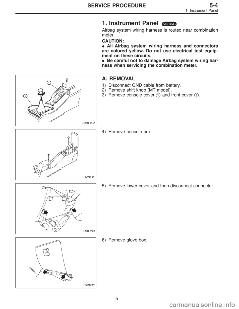
1. Instrument Panel
Airbag system wiring harness is routed near combination
meter.
CAUTION:
�All Airbag system wiring harness and connectors
are colored yellow. Do not use electrical test equip-
ment on these circuits.
�Be careful not to damage Airbag system wiring har-
ness when servicing the combination meter.
B5M0022A
A: REMOVAL
1) Disconnect GND cable from battery.
2) Remove shift knob (MT model).
3) Remove console cover�
1and front cover�2.
B5M0023
4) Remove console box.
B5M0024A
5) Remove lower cover and then disconnect connector.
B5M0025
6) Remove glove box.
5
5-4SERVICE PROCEDURE
1. Instrument Panel
Page 1096 of 2248
, 100 minutes (AT)
Cold cranking ampere 430 amperes (MT), 490 amperes (AT)
Fuse10 A, 15 A, 20 A
Combination
meterSpeedometer")
1. Body Electrical
A: SPECIFICATIONS
BatteryReserve capacity 82 minutes (MT), 100 minutes (AT)
Cold cranking ampere 430 amperes (MT), 490 amperes (AT)
Fuse10 A, 15 A, 20 A
Combination
meterSpeedometer Electric pulse type
Tachometer Electric impulse type
Water temperature gauge Thermistor cross coil type
Fuel gauge Resistance cross coil type
Charge indicator light 12 V—1.4 W
Brake fluid level warning/parking brake indicator light 12 V—1.4 W
AT oil temperature warning light (AWD only) 12 V—1.4 W
A.B.S. warning light 12 V—1.4 W
CHECK ENGINE warning light
(Malfunction indicator lamp)12 V—1.4 W
Oil pressure warning light 12 V—1.4 W
AIRBAG system warning light 12 V—1.4 W
Low fuel warning light 12 V—3W
FWD indicator light 12 V—1.4 W
TCS warning light 12 V—1.4 W
TCS indicator light 12 V—1.4 W
Turn signal indicator light 12 V—1.4 W (2 pieces)
Seat belt warning light 12 V—1.4 W
Door open warning light 12 V—1.4 W
Headlight beam indicator light 12 V—1.4 W
Meter illumination light12 V—3 W (2 pieces)
12 V—3.4 W (4 pieces)
Headlight 12 V—60/55 W (Halogen)
Front clearance light 12 V—5W
Turn signal lightFront 12 V—21 W
Rear 12 V—21 W
Tail/Stop light 12 V—5/21 W
Back-up light 12 V—21 W
High-mount stop light12 V—18 W (SEDAN), 12 V—13 W
(WAGON)
License plate light 12 V—5W
Room light 12 V—8W
Trunk room light (SEDAN) 12 V—5W
Luggage room light (WAGON) 12 V—5W
Spot light 12 V—8 W (2 pieces)
Glove box light 12 V—3.4 W
Ash tray illumination light 12 V—1.7 W
Selector lever illumination light (AT model) 12 V—1.7 W
2
6-2SPECIFICATIONS
1. Body Electrical
Page 1143 of 2248
17. Power Door Lock
A: REMOVAL AND INSTALLATION
1. FRONT AND REAR DOOR, AND REAR GATE LOCK
ACTUATOR
Refer to 5-2 [W2A7] as for removal and installation of front
door lock actuator, rear door lock actuators, and rear gate
lock actuator.
NOTE:
To remove and install the actuators, it is necessary to dis-
assemble the door component parts.
B6M0351A
2. DOOR LOCK TIMER
1) Remove glove box.
2) Remove back pocket cover.
3) Remove two bolts located at the rear of back pocket
cover.
4) Remove instrument panel side right cover and bolt.
5) Remove clip located at the inside end of instrument
panel.
6) Remove nut which secures door lock timer, and remove
door lock timer from bracket while pulling right side lower
end of instrument panel.
CAUTION:
Be careful not to damage instrument panel while pull-
ing its right side lower end.
7) Disconnect connector from door lock timer.
8) Installation is in the reverse order of removal.
41
6-2SERVICE PROCEDURE
17. Power Door Lock
Page 2210 of 2248

Connector Connecting to
No. Pole Color Area No. Name
i1 22 Black C-2 B36
Bulkhead wiring harness i2 22 * C-1 B37
i3 22 Brown C-1 B38
i4 20 Blue C-2 B39
i5 15 Gray C-1 F/B
i6 10 * C-1 Remote control rearview mirror switch
i7 6 Yellow B-2 Front fog light switch
i8 4 Brown B-2 Security indicator light
i9 6 * B-2 T.C.S. off switch
i10 16 Light gray B-2
Combination meter
i11 3 * B-2
i12 16 Light gray B-2 Combination meter
i13 4 * B-2 Combination meter (Airbag warning)
i14 13 * B-2 Combination meter
i15 6 * B-3 Fan switch
i16 3 * B-3 A/C switch
i17 16 * B-3 Mode control panel
i18 6 * B-3 Rear defogger switch
i19 6 Brown B-2 Cruise control main switch
i20 4 Blue B-3 B80 Bulkhead wiring harness
i21 2 Black C-3 Ash tray illumination light
i22 10 * B-3 Hazard switch
i23 2 Brown B-4 Glove box illumination light
i24 1 * C-3
Cigarette lighter
i25 3 * C-3
i26 14 * B-3 Radio
i27 2 * B-3 CD player illumination light
i28 1 Black C-3 Ground
i29 1 Black C-3 Ground (Radio)
*: Non-colored
124
6-3WIRING DIAGRAM
8. Electrical Wiring Harness and Ground Point
![SUBARU LEGACY 1995 Service Repair Manual 7) Installation is in the reverse order of removal.
Fitted length of heater hose over pipe:
25 — 30 mm (0.98 — 1.18 in)
8) Pour coolant. <Ref. to 2-5 [W1B0].>
B5M0025
3. Blower Motor Assembly
A: R](/manual-img/17/57432/w960_57432-852.png "SUBARU LEGACY 1995 Service Repair Manual 7) Installation is in the reverse order of removal.
Fitted length of heater hose over pipe:
25 — 30 mm (0.98 — 1.18 in)
8) Pour coolant. <Ref. to 2-5 [W1B0].>
B5M0025
3. Blower Motor Assembly
A: R")
![SUBARU LEGACY 1995 Service Repair Manual 7) Installation is in the reverse order of removal.
Fitted length of heater hose over pipe:
25 — 30 mm (0.98 — 1.18 in)
8) Pour coolant. <Ref. to 2-5 [W1B0].>
B5M0025
3. Blower Motor Assembly
A: R](/manual-img/17/57432/w960_57432-853.png "SUBARU LEGACY 1995 Service Repair Manual 7) Installation is in the reverse order of removal.
Fitted length of heater hose over pipe:
25 — 30 mm (0.98 — 1.18 in)
8) Pour coolant. <Ref. to 2-5 [W1B0].>
B5M0025
3. Blower Motor Assembly
A: R")
![SUBARU LEGACY 1995 Service Repair Manual B5M0025
5. Intake Door Motor
A: REMOVAL
1) Disconnect GND cable from battery.
2) Remove glove box and pocket back panel. <Ref. to 5-4
[W1A0].>
3) Remove heater duct or evaporator. (With A/C model).
<R](/manual-img/17/57432/w960_57432-857.png "SUBARU LEGACY 1995 Service Repair Manual B5M0025
5. Intake Door Motor
A: REMOVAL
1) Disconnect GND cable from battery.
2) Remove glove box and pocket back panel. <Ref. to 5-4
[W1A0].>
3) Remove heater duct or evaporator. (With A/C model).
<R")
![SUBARU LEGACY 1995 Service Repair Manual G4M0641
14. Evaporator Module
A: REMOVAL AND INSTALLATION
1) Disconnect battery negative terminal.
2) Discharge refrigerant using refrigerant recovery system.
<Ref. to 4-7 [W601].>
3) Disconnect disch](/manual-img/17/57432/w960_57432-898.png "SUBARU LEGACY 1995 Service Repair Manual G4M0641
14. Evaporator Module
A: REMOVAL AND INSTALLATION
1) Disconnect battery negative terminal.
2) Discharge refrigerant using refrigerant recovery system.
<Ref. to 4-7 [W601].>
3) Disconnect disch")
![SUBARU LEGACY 1995 Service Repair Manual 17. Power Door Lock
A: REMOVAL AND INSTALLATION
1. FRONT AND REAR DOOR, AND REAR GATE LOCK
ACTUATOR
Refer to 5-2 [W2A7] as for removal and installation of front
door lock actuator, rear door lock actu](/manual-img/17/57432/w960_57432-1142.png "SUBARU LEGACY 1995 Service Repair Manual 17. Power Door Lock
A: REMOVAL AND INSTALLATION
1. FRONT AND REAR DOOR, AND REAR GATE LOCK
ACTUATOR
Refer to 5-2 [W2A7] as for removal and installation of front
door lock actuator, rear door lock actu")