Page 40 of 2248
 Check timing belt teeth for breaks, cracks, and wear. If
any fault is found, replace belt.
2) Check the condition of back side of belt; if any crack is
found, replace b")
B: INSPECTION
1. TIMING BELT
1) Check timing belt teeth for breaks, cracks, and wear. If
any fault is found, replace belt.
2) Check the condition of back side of belt; if any crack is
found, replace belt.
CAUTION:
�Be careful not to let oil, grease or coolant contact
the belt. Remove quickly and thoroughly if this hap-
pens.
G2M0115
�Do not bend the belt sharply.
Bending radius: h
60 mm (2.36 in) or more
2. BELT TENSION ADJUSTER
1) Visually check oil seals for leaks, and rod ends for
abnormal wear or scratches. If necessary, replace belt ten-
sion adjuster.
CAUTION:
Slight traces of oil at rod’s oil seal does not indicate a
problem.
2) While holding tensioner with both hands, push the rod
section against floor or wall ensuring the rod section will
react as follows:
(1) When applying a force of 147 N (15 kg, 33 lb), the
rod section should not sink.
(2) When applying a force of 147 to 490 N (15 to 50 kg,
33 to 110 lb), the rod section should maintain a projec-
tionally acting force and should not sink within 8.5 sec-
onds.
20
2-3SERVICE PROCEDURE
3. Timing Belt
Page 227 of 2248
 Check")
B2M0173A
B: INSPECTION
1. RELEASE BEARING
CAUTION:
Since this bearing is grease sealed and is of a nonlu-
brication type, do not wash with gasoline or any sol-
vent when servicing the clutch.
1) Check the bearing for smooth movement by applying
force in the radial direction.
Radial direction stroke:
FWD; Approx.
1.0 mm (0.039 in)
AWD; Approx.
1.4 mm (0.055 in)
G2M0240
2) Check the bearing for smooth rotation by applying pres-
sure in the thrust direction.
3) Check wear and damage of bearing case surface con-
tacting with lever.
G2M0241
2. RELEASE LEVER
Check lever pivot portion and the point of contact with
release bearing case for wear.
C: INSTALLATION
CAUTION:
Before or during assembling, lubricate the following
points with a light coat of grease.
�Inner groove of release bearing
�Contact surface of lever and pivot
�Contact surface of lever and bearing
�Transmission main shaft spline (Use grease contain-
ing molybdenum disulphide.)
6
2-10SERVICE PROCEDURE
3. Release Bearing and Lever
Page 228 of 2248
 While pushing release lever�
3to pivot and twisting it to
both sides, fit retainer spring�
5onto the constricted portion
of pivot.
NOTE:
Confirm that retaine")
B2M0633A
1. MECHANICAL APPLICATION TYPE
1) While pushing release lever�
3to pivot and twisting it to
both sides, fit retainer spring�
5onto the constricted portion
of pivot.
NOTE:
Confirm that retainer spring is securely fitted by observing
it through the main case hole.
2) Install release bearing�
6and fasten it with two clips�2.
3) Install release lever seal�
4.
G2M0235
4) After remounting engine and transmission on body,
make adjustment of the clutch release lever end play.
CAUTION:
Take care not to twist the cable during adjustment.
5) Install release lever return spring (Models without hill
holder only).
NOTE:
Hook up the return spring to right side hole of the release
lever.
G2M0242
4. Clutch Disc and Cover
A: REMOVAL
1) Install ST on flywheel.
ST 498497100 CRANKSHAFT STOPPER
2) Remove clutch cover and clutch disc.
CAUTION:
�Take care not to allow oil on the clutch disc facing.
�Do not disassemble either clutch cover or clutch
disc.
G2M0243
3) Remove flywheel.
7
2-10SERVICE PROCEDURE
3. Release Bearing and Lever - 4. Clutch Disc and Cover
Page 229 of 2248
 While pushing release lever�
3to pivot and twisting it to
both sides, fit retainer spring�
5onto the constricted portion
of pivot.
NOTE:
Confirm that retaine")
B2M0633A
1. MECHANICAL APPLICATION TYPE
1) While pushing release lever�
3to pivot and twisting it to
both sides, fit retainer spring�
5onto the constricted portion
of pivot.
NOTE:
Confirm that retainer spring is securely fitted by observing
it through the main case hole.
2) Install release bearing�
6and fasten it with two clips�2.
3) Install release lever seal�
4.
G2M0235
4) After remounting engine and transmission on body,
make adjustment of the clutch release lever end play.
CAUTION:
Take care not to twist the cable during adjustment.
5) Install release lever return spring (Models without hill
holder only).
NOTE:
Hook up the return spring to right side hole of the release
lever.
G2M0242
4. Clutch Disc and Cover
A: REMOVAL
1) Install ST on flywheel.
ST 498497100 CRANKSHAFT STOPPER
2) Remove clutch cover and clutch disc.
CAUTION:
�Take care not to allow oil on the clutch disc facing.
�Do not disassemble either clutch cover or clutch
disc.
G2M0243
3) Remove flywheel.
7
2-10SERVICE PROCEDURE
3. Release Bearing and Lever - 4. Clutch Disc and Cover
Page 287 of 2248
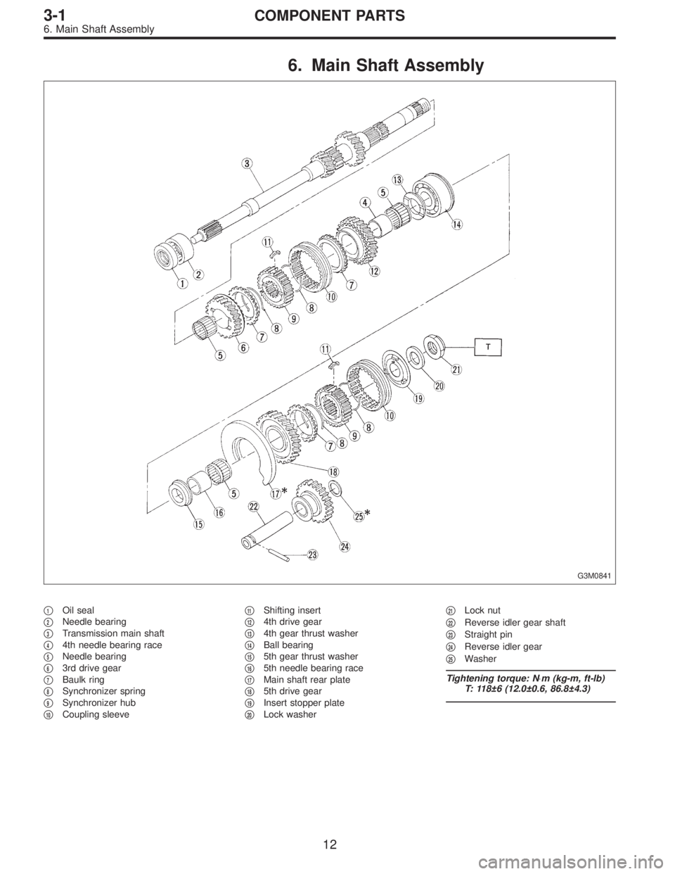
6. Main Shaft Assembly
G3M0841
�1Oil seal
�
2Needle bearing
�
3Transmission main shaft
�
44th needle bearing race
�
5Needle bearing
�
63rd drive gear
�
7Baulk ring
�
8Synchronizer spring
�
9Synchronizer hub
�
10Coupling sleeve�
11Shifting insert
�
124th drive gear
�
134th gear thrust washer
�
14Ball bearing
�
155th gear thrust washer
�
165th needle bearing race
�
17Main shaft rear plate
�
185th drive gear
�
19Insert stopper plate
�
20Lock washer�
21Lock nut
�
22Reverse idler gear shaft
�
23Straight pin
�
24Reverse idler gear
�
25Washer
Tightening torque: N⋅m (kg-m, ft-lb)
T: 118±6 (12.0±0.6, 86.8±4.3)
12
3-1COMPONENT PARTS
6. Main Shaft Assembly
Page 309 of 2248
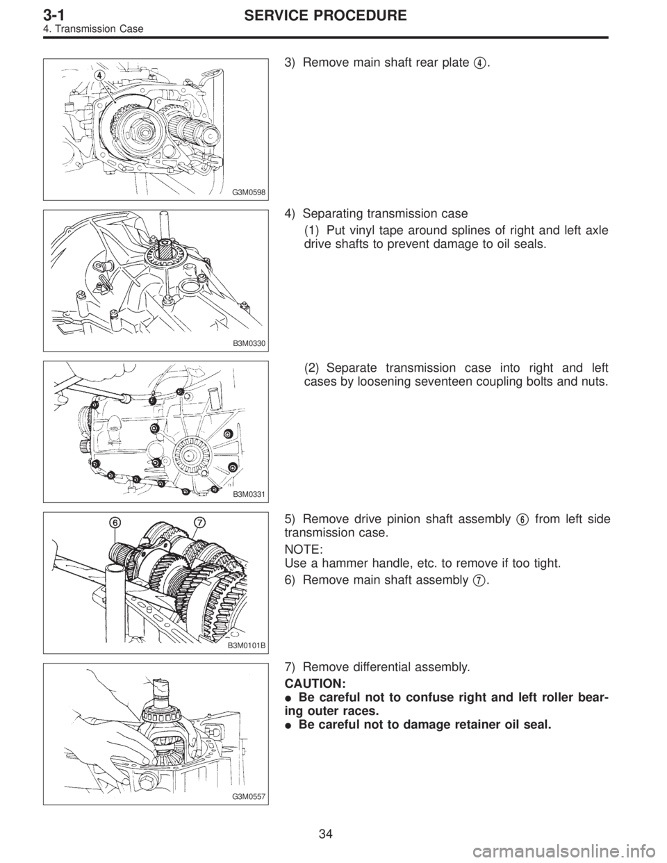
G3M0598
3) Remove main shaft rear plate�4.
B3M0330
4) Separating transmission case
(1) Put vinyl tape around splines of right and left axle
drive shafts to prevent damage to oil seals.
B3M0331
(2) Separate transmission case into right and left
cases by loosening seventeen coupling bolts and nuts.
B3M0101B
5) Remove drive pinion shaft assembly�6from left side
transmission case.
NOTE:
Use a hammer handle, etc. to remove if too tight.
6) Remove main shaft assembly�
7.
G3M0557
7) Remove differential assembly.
CAUTION:
�Be careful not to confuse right and left roller bear-
ing outer races.
�Be careful not to damage retainer oil seal.
34
3-1SERVICE PROCEDURE
4. Transmission Case
Page 318 of 2248
 Install differential assembly�3on left hand transmission
case.
CAUTION:
Be careful not to fold the sealing lip of oil seal.
NOTE:
Wrap the left and right splined sections of axle shaft with")
G3M0557
3) Install differential assembly�3on left hand transmission
case.
CAUTION:
Be careful not to fold the sealing lip of oil seal.
NOTE:
Wrap the left and right splined sections of axle shaft with
vinyl tape to prevent scratches.
G3M0558
4) Install needle bearing and oil seal onto the front of
transmission main shaft assembly�
4, and position in left
side transmission case.
CAUTION:
�Wrap clutch splined section with vinyl tape to pre-
vent damage to oil seal.
�Apply grease (Unilube #2 or equivalent) to the seal-
ing lip of oil seal.
NOTE:
�Align the end face of seal with surface A of left side
transmission main case when installing oil seal.
�Be careful not to drop oil seal when installing right side
transmission main case.
�Make sure straight pin is positioned in hole in needle
bearing’s outer race.
G3M0575
5) Install drive pinion shaft assembly�5with shims
selected before into transmission case.
NOTE:
Ensure that the knock pin of the case is fitted into the hole
in the bearing outer race.
43
3-1SERVICE PROCEDURE
4. Transmission Case
Page 335 of 2248
 Put vinyl tape around main shaft splines to protect oil
seal from damage. Then pull out oil seal and needle bear-
ing by hand.
2) Remove lock nut from")
B3M0087A
7. Main Shaft Assembly
A: DISASSEMBLY
1) Put vinyl tape around main shaft splines to protect oil
seal from damage. Then pull out oil seal and needle bear-
ing by hand.
2) Remove lock nut from transmission main shaft assem-
bly.
NOTE:
Remove caulking before taking off lock nut.
ST1 498937000 TRANSMISSION HOLDER
ST2 499987003 SOCKET WRENCH (35)
G3M0644
3) Remove insert stopper plate�1, sleeve and hub assem-
bly No. 2, baulk ring�
3, 5th drive gear�4, and needle
bearing�
5(32 x 36 x 25.7).
G3M0645
4) Using ST1, ST2 and a press, remove:
�5th needle bearing inner race�
1
�5th gear thrust washer�2
�Ball bearing�3(25.5 x 65 x 31)
�4th gear thrust washer�
4
�4th drive gear�5
�Sleeve and hub assembly�6
�Baulk ring�7
�4th needle bearing�8
�4th needle bearing inner race�9
�3rd drive gear�10
ST1 899864100 REMOVER
ST2 899714110 REMOVER
NOTE:
Replace sleeve and hub with new ones. Do not attempt to
disassemble because they must engage at a specified
point. If they should be disassembled, mark engagement
point on splines beforehand.
60
3-1SERVICE PROCEDURE
7. Main Shaft Assembly