Page 16 of 2248
5) Check idle speed when unloaded. (With headlights,
heater fan, rear defroster, radiator fan, air conditioning, etc.
OFF)
Idle speed (No load and gears in neutral (MT) or N or
P (AT) position):
700±100 rpm
6) Check idle speed when loaded. (Turn air conditioning
switch to“ON”and operate compressor for at least one
minute before measurement.)
Idle speed [A/C“ON”, no load and gears in neutral
(MT) or N or P (AT) position]:
850±50 rpm
CAUTION:
Never rotate idle adjusting screw. If idle speed is out
of specifications, refer to General On-board Diagnosis
Table under “2-7 On-Board Diagnostics II System”.
4
2-2
3. Engine Idle Speed
Page 117 of 2248
 Approx. 6.1 (6.4, 5.4)
Engine
coolant
pum")
1. Engine Cooling System
A: SPECIFICATIONS
Cooling systemElectric fan + Forced engine coolant circulation
system
Total engine coolant capacity�(US qt, Imp qt) Approx. 6.1 (6.4, 5.4)
Engine
coolant
pumpTypeCentrifugal impeller type
Discharge performance IDischarge 20�(5.3 US gal, 4.4 Imp gal)/min.
Pump speed—total engine cool-
ant head760 rpm — 0.3 mAq (1.0 ftAq)
Engine coolant temperature 85°C (185°F)
Discharge performance IIDischarge 100�(26.4 US gal, 22.0 Imp gal)/min.
Pump speed—total engine cool-
ant head3,000 rpm — 5.0 mAq (16.4 ftAq)
Engine coolant temperature 85°C (185°F)
Discharge performance IIIDischarge 200�(52.8 US gal, 44.0 Imp gal)/min.
Pump speed—total engine cool-
ant head6,000 rpm — 23.0 mAq (75.5 ftAq)
Engine coolant temperature 85°C (185°F)
Impeller diameter 76 mm (2.99 in)
Number of impeller vanes 8
Pump pulley diameter 60 mm (2.36 in)
ThermostatTypeWax pellet type
Starts to open 76 — 80°C (169 — 176°F)
Fully opened91°C (196°F)
Valve lift9.0 mm (0.354 in) or more
Valve bore35 mm (1.38 in)
Radiator fanMotor120 W
Fan diameter x Blade 320 mm (12.60 in) x 5
RadiatorTypeCross flow, pressure type
Core dimensions670x361x16mm
(26.38 x 14.21 x 0.63 in)
Pressure range in which cap valve is openAbove: 88±10 kPa
(0.9±0.1 kg/cm
2, 12.8±1.4 psi)
Below: �4.9 to �9.8 kPa
(�0.05 to �0.1 kg/cm
2, �0.7 to �1.4 psi)
FinsCorrugated fin type
Reservoir
tankCapacity 0.5�(0.5 US qt, 0.4 Imp qt)
B: SERVICE DATA
Engine
coolant
pumpClearance between impeller and caseStandard
Limit0.5 — 0.7 mm (0.020 — 0.028 in)
1.0 mm (0.039 in)
“Thrust” runout of impeller end 0.5 mm (0.020 in)
2
2-5SPECIFICATIONS AND SERVICE DATA
1. Engine Cooling System
Page 119 of 2248
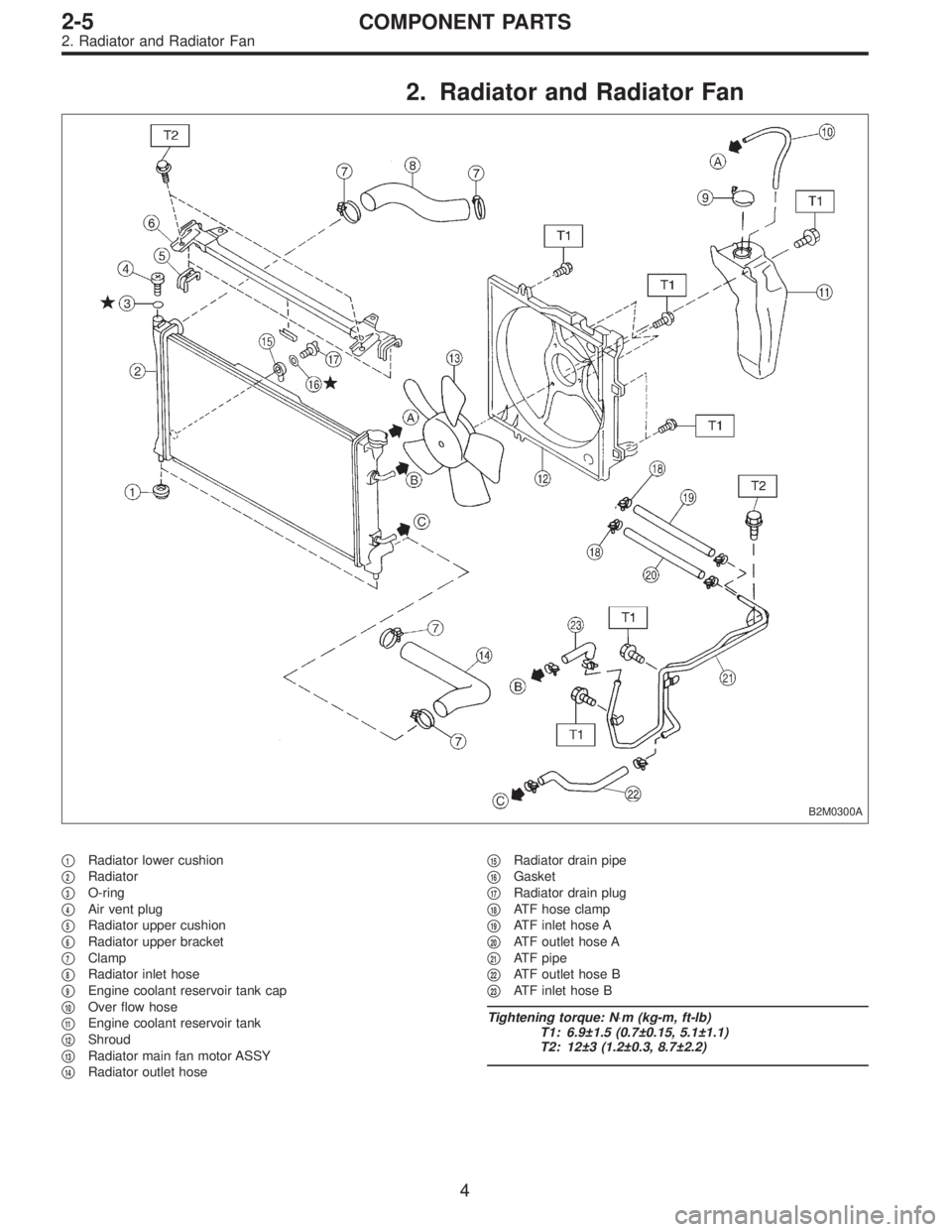
2. Radiator and Radiator Fan
B2M0300A
�1Radiator lower cushion
�
2Radiator
�
3O-ring
�
4Air vent plug
�
5Radiator upper cushion
�
6Radiator upper bracket
�
7Clamp
�
8Radiator inlet hose
�
9Engine coolant reservoir tank cap
�
10Over flow hose
�
11Engine coolant reservoir tank
�
12Shroud
�
13Radiator main fan motor ASSY
�
14Radiator outlet hose�
15Radiator drain pipe
�
16Gasket
�
17Radiator drain plug
�
18ATF hose clamp
�
19ATF inlet hose A
�
20ATF outlet hose A
�
21ATF pipe
�
22ATF outlet hose B
�
23ATF inlet hose B
Tightening torque: N⋅m (kg-m, ft-lb)
T1: 6.9±1.5 (0.7±0.15, 5.1±1.1)
T2: 12±3 (1.2±0.3, 8.7±2.2)
4
2-5COMPONENT PARTS
2. Radiator and Radiator Fan
Page 123 of 2248
G6M0095
2. Engine Coolant Pump
A: REMOVAL
1) Open engine hood.
2) Disconnect ground cable from the battery.
B2M0015A
3) Drain engine coolant completely.
B2M0137
4) Disconnect radiator outlet hose from engine coolant
pump.
B2M0323
5) Remove radiator fan motor assembly.
G2M0286
6) Remove V-belt(s).
8
2-5SERVICE PROCEDURE
2. Engine Coolant Pump
Page 128 of 2248
B2M0015A
4. Radiator
A: REMOVAL
1) Disconnect battery cables and remove battery from
body.
2) Drain engine coolant.
Set container under the vehicle, and remove drain cock
from radiator.
B2M0304
3) Disconnect radiator outlet hose from thermostat cover.
4) Disconnect ATF cooler hoses from radiator. (AT model)
B2M0017
5) Remove V-belt cover.
B2M0305
6) Disconnect inlet hose from radiator.
G2M0263
7) Disconnect connectors of radiator main fan and sub fan
motor.
12
2-5SERVICE PROCEDURE
4. Radiator
Page 130 of 2248
B2M0320
3) Install radiator brackets and tighten bolts.
4) Connect radiator main fan motor and sub fan motor
connectors.
B2M0137
5) Connect radiator inlet and outlet hoses.
6) Connect ATF cooler hoses. (AT model)
B2M0017
7) Install V-belt cover.
G6M0095
8) Connect ground cable to battery terminal.
14
2-5SERVICE PROCEDURE
4. Radiator
Page 131 of 2248
G2M0223
5. Radiator Cap
A: INSPECTION
1) Attach radiator cap to tester.
2) Increase pressure until tester gauge pointer stops.
Radiator cap is functioning properly if it holds the service
limit pressure for five to six seconds.
Standard pressure:
78—98 kPa (0.8—1.0 kg/cm
2,11—14 psi)
Service limit pressure:
69 kPa (0.7 kg/cm
2, 10 psi)
CAUTION:
Be sure to remove foreign matter and rust from the cap
in advance; otherwise, results of pressure test will be
incorrect.
G2M0263
6. Radiator Fan and Fan Motor
A: REMOVAL
1) Disconnect ground cable from battery terminal.
2) Disconnect connector of fan motor.
G2M0224
3) Remove reservoir tank.
B2M0308
4) Remove four bolts holding shroud to radiator.
15
2-5SERVICE PROCEDURE
5. Radiator Cap - 6. Radiator Fan and Fan Motor
Page 132 of 2248
G2M0223
5. Radiator Cap
A: INSPECTION
1) Attach radiator cap to tester.
2) Increase pressure until tester gauge pointer stops.
Radiator cap is functioning properly if it holds the service
limit pressure for five to six seconds.
Standard pressure:
78—98 kPa (0.8—1.0 kg/cm
2,11—14 psi)
Service limit pressure:
69 kPa (0.7 kg/cm
2, 10 psi)
CAUTION:
Be sure to remove foreign matter and rust from the cap
in advance; otherwise, results of pressure test will be
incorrect.
G2M0263
6. Radiator Fan and Fan Motor
A: REMOVAL
1) Disconnect ground cable from battery terminal.
2) Disconnect connector of fan motor.
G2M0224
3) Remove reservoir tank.
B2M0308
4) Remove four bolts holding shroud to radiator.
15
2-5SERVICE PROCEDURE
5. Radiator Cap - 6. Radiator Fan and Fan Motor
 Check idle speed when unloaded. (With headlights,
heater fan, rear defroster, radiator fan, air conditioning, etc.
OFF)
Idle speed (No load and gears in neutral (MT) or N or
P (AT) position):
700±")
![SUBARU LEGACY 1995 Service Repair Manual G6M0095
2. Engine Coolant Pump
A: REMOVAL
1) Open engine hood.
2) Disconnect ground cable from the battery.
B2M0015A
3) Drain engine coolant completely.
<Ref. to 2-5 [W1A0].>
B2M0137
4) Disconnect rad](/manual-img/17/57432/w960_57432-122.png "SUBARU LEGACY 1995 Service Repair Manual G6M0095
2. Engine Coolant Pump
A: REMOVAL
1) Open engine hood.
2) Disconnect ground cable from the battery.
B2M0015A
3) Drain engine coolant completely.
<Ref. to 2-5 [W1A0].>
B2M0137
4) Disconnect rad")
 Disconnect battery cables and remove battery from
body.
2) Drain engine coolant.
Set container under the vehicle, and remove drain cock
from radiator.
B2M0304
3) Dis")
 Install radiator brackets and tighten bolts.
4) Connect radiator main fan motor and sub fan motor
connectors.
B2M0137
5) Connect radiator inlet and outlet hoses.
6) Connect ATF cooler hoses")
 Attach radiator cap to tester.
2) Increase pressure until tester gauge pointer stops.
Radiator cap is functioning properly if it holds the service
limit pressu")
 Attach radiator cap to tester.
2) Increase pressure until tester gauge pointer stops.
Radiator cap is functioning properly if it holds the service
limit pressu")