Page 70 of 2248
(7) Further tighten all bolts by 80 to 90°in numerical
sequence.
CAUTION:
Ensure that the total“re-tightening angle”[steps (6)
and (7) above] do not exceed 180°.
3) Install oil level gauge guide attaching bolt (left side
only).
4) Install timing belt, camshaft sprocket and related parts.
2. INTAKE MANIFOLD
CAUTION:
Use dry compressed air to remove foreign particles
before installing each solenoid valve and sensor.
1) Install engine coolant pipe.
2) Install intake manifold.
3) Remove ENGINE STAND (ST).
49
2-3SERVICE PROCEDURE
6. Cylinder Head
Page 99 of 2248

2. Engine Noise
Valve lash adjusters may make clicking noise once engine
starts. It is normal if clicking noise ceases after a few min-
utes.
If clicking noise continues after a few minutes, check
engine oil level and add oil if necessary.
Then, do as follows to cease clicking noise.
1) Warm-up engine for five minutes.
2) Turn ignition switch OFF.
3) Connect test mode connector.
4) Start the engine and run it at approximately 2,000 rpm
for twenty minutes.
5) Turn ignition switch OFF.
6) Disconnect test mode connector.
7) Start the engine and check that clicking noise is ceased.
If noise still exists, conduct troubleshooting procedures in
accordance with the following table.
CAUTION:
Do not disconnect spark plug cord while engine is run-
ning.
Type of sound Condition Possible cause
Regular clicking soundSound increases as engine
speed increases.Valve mechanism is defective.
�Broken lash adjuster
�Worn valve rocker
�Worn camshaft
�Broken valve spring
�Worn valve lifter hole
Heavy and dull clankOil pressure is low.�Worn crankshaft main bearing
�Worn connecting rod bearing (big end)
Oil pressure is normal.�Loose flywheel mounting bolts
�Damaged engine mounting
High-pitched clank
(Spark knock)Sound is noticeable when
accelerating with an overload.�Ignition timing advanced
�Accumulation of carbon inside combustion chamber
�Wrong spark plug
�Improper gasoline
Clank when engine speed is
medium (1,000 to 2,000 rpm).Sound is reduced when fuel
injector connector of noisy
cylinder is disconnected.
(NOTE*)�Worn crankshaft main bearing
�Worn bearing at crankshaft end of connecting rod
Knocking sound when engine
is operating under idling speed
and engine is warm.Sound is reduced when fuel
injector connector of noisy
cylinder is disconnected.
(NOTE*)�Worn cylinder liner and piston ring
�Broken or stuck piston ring
�Worn piston pin and hole at piston end of connecting rod
Sound is not reduced if each
fuel injector connector is
disconnected in turn. (NOTE*)�Unusually worn valve lifter
�Worn cam gear
�Worn camshaft journal bore in crankcase
Squeaky sound—�Insufficient generator lubrication
Rubbing sound—�Defective generator brush and rotor contact
Gear scream when starting
engine—�Defective ignition starter switch
�Worn gear and starter pinion
Sound like polishing glass with
a dry cloth—�Loose drive belt
�Defective engine coolant pump shaft
78
2-3DIAGNOSTICS
2. Engine Noise
Page 122 of 2248
 Fill engine coolant into reservoir tank up to upper level.
4) Attach radiator cap and reservoir tank cap properly.
5) Install air vent plug.
6) Warm-up engine completely for more than five")
B2M0140
3) Fill engine coolant into reservoir tank up to upper level.
4) Attach radiator cap and reservoir tank cap properly.
5) Install air vent plug.
6) Warm-up engine completely for more than five minutes
at 2,000 to 3,000 rpm.
7) Stop engine and wait until temperature drops to a safe
level.
8) If engine coolant level drops in radiator, add engine
coolant to filler neck position.
9) If engine coolant level drops from upper level of reser-
voir tank, add engine coolant to upper level.
10) Attach radiator cap and reservoir tank cap properly.
B2M0136
C: CHECKING OF COOLING SYSTEM
1) Remove radiator cap, top off radiator, and attach tester
to radiator in place of cap.
2) Apply a pressure of 157 kPa (1.6 kg/cm
2, 23 psi) to
radiator to check if:
(1) Engine coolant leaks at/around radiator.
(2) Engine coolant leaks at/around hoses or connec-
tions.
CAUTION:
�Engine should be off.
�Wipe engine coolant from check points in advance.
�Be careful to prevent engine coolant from spurting
out when removing tester.
�Be careful also not to deform filler neck of radiator
when installing or removing tester.
7
2-5SERVICE PROCEDURE
1. On-Car Service
Page 252 of 2248

B: INSTALLATION
1. Install engine to transmission.
2. Tighten bolts which hold upper side of transmission to engine.
3. Remove lifting device and wire rope.
4. Remove garage jack.
5. Install pitching stopper.
AT model
6. Install torque converter onto drive plate.
7. Install canister and bracket.
8. Install power steering pump on bracket.
9. Tighten nuts which hold lower side of transmission to engine.
10. Tighten nuts which install front cushion rubber onto cross-
member.
11. Install front exhaust pipe and center exhaust pipe.
12. Connect hoses, connectors and cables.
13. Install air intake system.
�Air intake duct
�Air cleaner element and upper cover.
With A/C
14. Install A/C pressure hoses.
15. Install cooling system.
16. Install battery onto the vehicle, and connect cables.
17. Fill coolant.
18. Check ATF level, and connect if necessary. [AT]
19. Correct power steering oil, and bleed air.
20. Remove front hood stay, and close front hood.
21. Take off the vehicle from lift arms.
�
�
�
�
�
�
�
�
�
�
�
�
18
2-11SERVICE PROCEDURE
2. Engine
Page 258 of 2248
G2M0267
(5) Connect radiator inlet hose.
B2M0016A
(6) Connect radiator outlet hose.
(7) Connect ATF cooler hoses. (AT model)
B2M0017
(8) Install V-belt cover.
16) Install battery in the vehicle, and connect cables.
17) Fill coolant.
18) Check ATF level and correct if necessary. (AT model)
19) Charge A/C system with refrigerant.
20) Remove front hood stay, and close front hood.
21) Take off the vehicle from lift arms.
24
2-11SERVICE PROCEDURE
2. Engine
Page 382 of 2248

3. Performance Test
A: STALL TEST
1. GENERAL
The stall test is of extreme importance in diagnosing the
condition of the automatic transmission and the engine. It
should be conducted to measure the engine stall speeds in
all shift ranges except the P and N ranges.
Purposes of the stall test:
1) To check the operation of the automatic transmission
clutch.
2) To check the operation of the torque converter clutch.
3) To check engine performance.
2. TEST METHODS
Preparations before test:
�
1Check that throttle valve opens fully.
�
2Check that engine oil level is correct.
�
3Check that coolant level is correct.
�
4Check that ATF level is correct.
�
5Check that differential gear oil level is correct.
�
6Increase ATF temperature to 60 to 80°C (140 to 176°F)
by idling the engine for approximately 30 minutes (with
select lever set to“N”or“P”).
1) Install an engine tachometer at a location visible from
the driver’s compartment and mark the stall speed range
on the tachometer scale.
2) Place the wheel chocks at the front and rear of all
wheels and engage the parking brake.
3) Move the manual linkage to ensure it operates properly,
and shift the select lever to the 2 range.
B3M0286B
4) While forcibly depressing the foot brake pedal, gradu-
ally depress the accelerator pedal until the engine operates
at full throttle.
38
3-2SERVICE PROCEDURE
3. Performance Test
Page 1380 of 2248
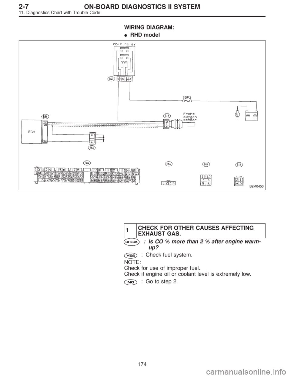
WIRING DIAGRAM:
�RHD model
B2M0450
1CHECK FOR OTHER CAUSES AFFECTING
EXHAUST GAS.
: Is CO % more than 2 % after engine warm-
up?
: Check fuel system.
NOTE:
Check for use of improper fuel.
Check if engine oil or coolant level is extremely low.
: Go to step 2.
174
2-7ON-BOARD DIAGNOSTICS II SYSTEM
11. Diagnostics Chart with Trouble Code
![SUBARU LEGACY 1995 Service Repair Manual (7) Further tighten all bolts by 80 to 90°in numerical
sequence.
CAUTION:
Ensure that the total“re-tightening angle”[steps (6)
and (7) above] do not exceed 180°.
3) Install oil level gauge guide](/manual-img/17/57432/w960_57432-69.png "SUBARU LEGACY 1995 Service Repair Manual (7) Further tighten all bolts by 80 to 90°in numerical
sequence.
CAUTION:
Ensure that the total“re-tightening angle”[steps (6)
and (7) above] do not exceed 180°.
3) Install oil level gauge guide")
 Connect radiator inlet hose.
B2M0016A
(6) Connect radiator outlet hose.
(7) Connect ATF cooler hoses. (AT model)
B2M0017
(8) Install V-belt cover.
16) Install battery in the vehicle, and c")