Page 889 of 2248
 Vehicle in shade
2) No wind
3) All vehicle doors clos")
10. Performance Test
1. VEHICLE SET UP
In order to obtain meaningful test results, the vehicle must
be set up to meet the following conditions:
1) Vehicle in shade
2) No wind
3) All vehicle doors closed
4) Front windows opened
5) Hood opened
6) Engine speed set at 1,500 rpm.
7) A/C ON
8) Temperature control lever—Maximum cold
9) Air source—Recirculation
10) Blower speed—4th position (High)
11) Operate A/C for 10 minutes (Minimum) before taking
measurement.
2. MEASUREMENTS
After 10 minutes (Minimum) of A/C operation and using
accurate test equipment, take the following measurements
(in order):
1) Evaporator intake air temperature at recirculation door.
2) Evaporator discharge air temperature at center grill.
3) Condenser (Ambient) intake air temperature measured
0.9 m (3 ft) in front and in line with the center of the con-
denser.
4) Suction (Low) side pressure
5) Discharge (High) side pressure
NOTE:
If only one thermometer is available; 1) take the ambient
measurement first; then 2) the intake air; and 3) dis-
charge air temperature.
29
4-7SERVICE PROCEDURE
10. Performance Test
Page 916 of 2248
 Operate the engine at approximately 1,500 rpm.
2) Open the door windows.
3) Set the fan switch to the 4th (High) position.
4) Set the mode selector")
9. Sight Glass Inspection
1. INSPECTION CONDITION
1) Operate the engine at approximately 1,500 rpm.
2) Open the door windows.
3) Set the fan switch to the 4th (High) position.
4) Set the mode selector switch to“A/C”position.
5) Set the temperature control switch to Full cold position.
6) Ensure that compressor discharge pressure is at least
588 kPa (6 kg/cm
2, 85 psi).
NOTE:
When discharge pressure does not reach 588 kPa (6
kg/cm
2, 85 psi) in areas where outside air temperature is
low, proceed as follows:
a. Set the TEMP. SWITCH to the Full hot position.
b. Set the temperature control switch to“MAX. A/C”posi-
tion.
c. Close the door windows completely.
d. Increase the compartment temperature so that dis-
charge pressure reaches at least 588 kPa (6 kg/cm
2,85
psi).
2. REFRIGERANT CHARGE AMOUNT CHECKING
Check the refrigerant charge amount using the following
table as a guide.
Item to check Adequate Insufficient Almost in refrigerant Too much refrigerant
State in sight glassCLEAR
Air bubbles sometimes
appear when engine
speed is increased or
decreased.
G4M0669
FOAMY or BUBBLY
Air bubbles always
appear.
G4M0670
FROSTY
Frost-like appears.
G4M0671
NO FOAM
No air bubbles appear.
G4M0672
Temperature of high
and low pressure linesHigh-pressure side is
hot while low-pressure
side is cold. (A big
temperature difference
between high and low
pressure side)High-pressure side is
warm and low-pressure
side is slightly cold.
(Not so big temperature
difference between high
and low pressure side)There is almost no
temperature difference
between high and low
pressure side.High-pressure side is
hot and low-pressure
side is slightly warm.
(Slight temperature
difference between high
and low pressure side)
Pressure of systemBoth pressures on high
and low pressure sides
are normal.Both pressures on high
and low pressure sides
are slightly low.High-pressure side is
abnormally low.Both pressures on high
and low pressure sides
are abnormally high.
54
4-7DIAGNOSTICS
9. Sight Glass Inspection
Page 980 of 2248
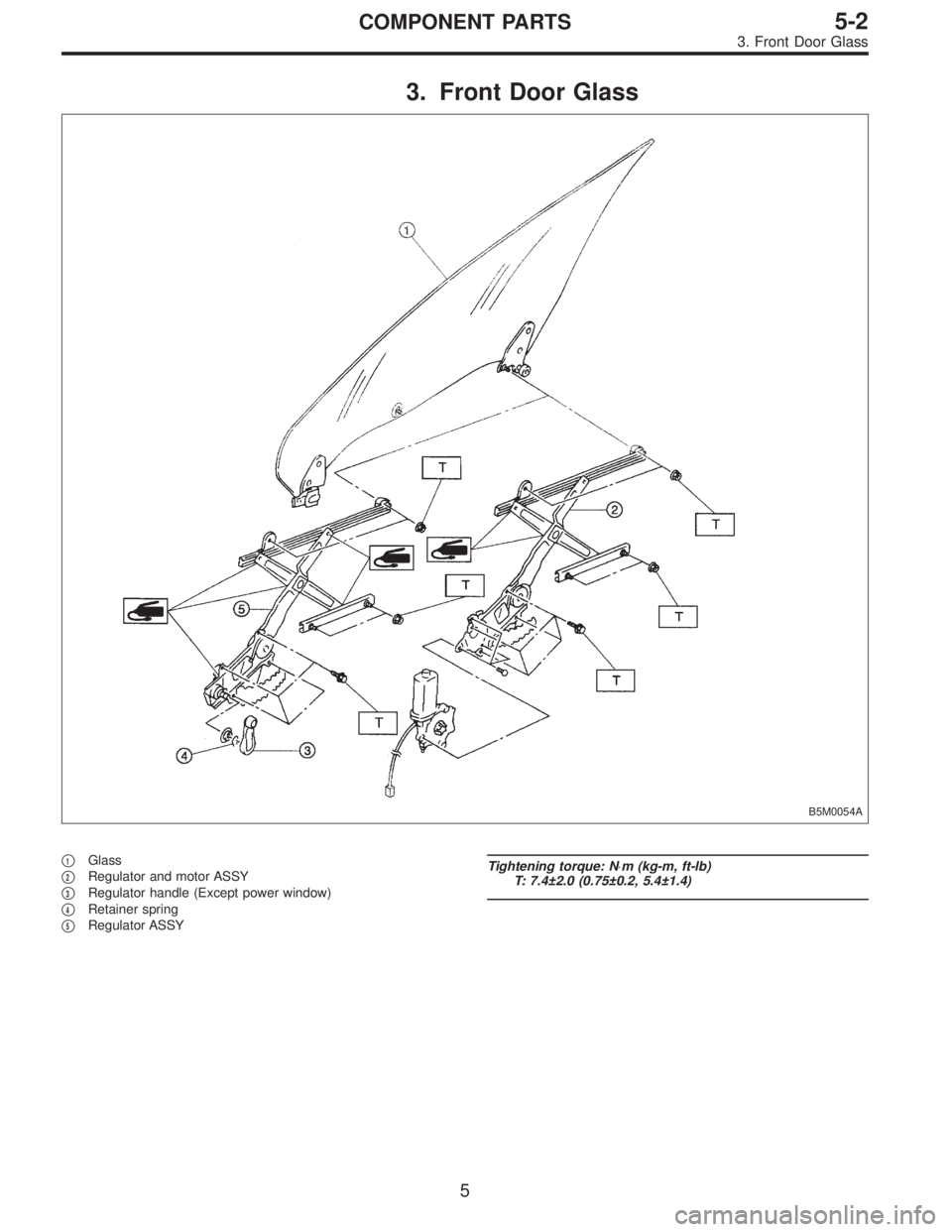
3. Front Door Glass
B5M0054A
�1Glass
�
2Regulator and motor ASSY
�
3Regulator handle (Except power window)
�
4Retainer spring
�
5Regulator ASSY
Tightening torque: N⋅m (kg-m, ft-lb)
T: 7.4±2.0 (0.75±0.2, 5.4±1.4)
5
5-2COMPONENT PARTS
3. Front Door Glass
Page 981 of 2248
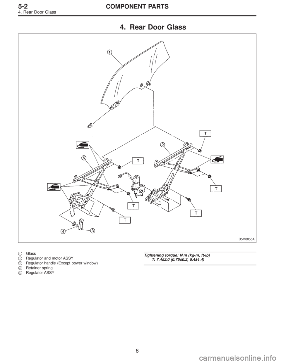
4. Rear Door Glass
B5M0055A
�1Glass
�
2Regulator and motor ASSY
�
3Regulator handle (Except power window)
�
4Retainer spring
�
5Regulator ASSY
Tightening torque: N⋅m (kg-m, ft-lb)
T: 7.4±2.0 (0.75±0.2, 5.4±1.4)
6
5-2COMPONENT PARTS
4. Rear Door Glass
Page 988 of 2248
G5M0486
2. Door
A: REMOVAL AND INSTALLATION
1. DOOR ASSY
1) Remove lower trim and disconnect connectors from
body harness.
2) Place a cloth or a wood block under door to prevent
damage, and support it with a jack.
3) Remove checker pin by driving it upward. Be careful not
to damage door and body.
G5M0385
4) Remove bolts (M8) securing upper and lower hinges to
door, and remove door from hinges.
Tightening torque:
25±3 N⋅m (2.5±0.3 kg-m, 18.1±2.2 ft-lb)
5) Remove hinges by loosening hinges mounting bolt (M8)
off of body.
Tightening torque:
29±5 N⋅m (3.0±0.5 kg-m, 21.7±3.6 ft-lb)
CAUTION:
Work carefully to avoid damaging door.
6) Installation is in the reverse order of removal.
NOTE:
Apply grease to moving parts of door hinges.
B5M0329A
2. TRIM PANEL
1) Press retainer spring�
1with a thin flat bladed screw-
driver and then remove regulator handle�
2. (models with-
out power window)
B5M0061A
2) Remove gusset cover�1and three screws.
13
5-2SERVICE PROCEDURE
2. Door
Page 989 of 2248
 Using ST, disengage the clip.
ST 925580000 PULLER
4) Remove trim panel and then disconnect connector.
(models with power window)
CAUTION:
Be careful not to break clip by applying undue forc")
G5M0390
3) Using ST, disengage the clip.
ST 925580000 PULLER
4) Remove trim panel and then disconnect connector.
(models with power window)
CAUTION:
Be careful not to break clip by applying undue force.
Installation is in the reverse order of removal.
G5M0391
3. SEALING COVER
1) Remove trim panel.
2) Remove speaker, remote assembly and disconnect
connectors.
3) Remove sealer with a spatula.
CAUTION:
Be careful because cover may break if sealer is
removed forcefully.
4) Install in reverse order of removal. Some special items
will be described below.
5) Confirm that sealer is properly applied without breaks.
Then install sealing cover.
6) When repairing or replacing sealing cover, use “CEME-
DINE 5430L” as sealer. It may be overlaid on existing
sealer.
Sealer:
CEMEDINE 5430L
B5M0062A
CAUTION:
�Any breaks in sealer can cause water leakage or
entry of air and dust. Be sure sealer is applied in a
continuous line.
�Do not stop up drain hole�
1with sealer.
�Do not stop up install hole�
2with sealing cover.
�Make sure sealing cover bonded areas are free from
wrinkles or openings.
14
5-2SERVICE PROCEDURE
2. Door
Page 990 of 2248
G5M0392
4. CHECKER
1) Remove trim panel.
2) Remove sealing cover.
3) Apply a cloth to door and body to prevent damaging
them, and remove checker pin by driving it upward.
CAUTION:
Be careful not to damage door and body.
4) Completely close door glass.
5) Loosen two nuts securing checker, and take out
checker through access hole in underside.
Installation should be made in the reverse order of
removal.
Tightening torque:
7.4±2.0 N⋅m (0.75±0.2 kg-m, 5.4±1.4 ft-lb)
5. DOOR GLASS
1) Remove trim panel.
2) Remove sealing cover.
3) Disconnect door mirror connector and then remove
gusset�
1.
4) Remove inner remote.
B5M0063A
5) Remove inner stabilizer�1.
B5M0064A
6) Remove nut and then separate glass holder�1from
guide channel A�
2.
NOTE:
When removing nut, move door window lower glass con-
necting section to service hole of door panel.
7) Remove window glass upward.
CAUTION:
After removing window glass, do not move regulator.
15
5-2SERVICE PROCEDURE
2. Door
Page 993 of 2248
B5M0068
8. OUTER HANDLE
1) Remove trim panel.
2) Remove sealing cover.
3) Detach door latch rod from outer handle and key lock.
4) Loosen nut securing outer handle and then remove
outer handle from outside.
CAUTION:
Be careful not to damage door.
Installation is in the reverse order of removal.
Tightening torque:
7.4±2.0 N⋅m (0.75±0.2 kg-m, 5.4±1.4 ft-lb)
B5M0069A
9. KEY LOCK
1) Remove trim panel.
2) Remove sealing cover.
3) Completely close door glass.
4) Remove outer handle.
5) Loosen spring�
1securing key lock.
6) Remove key lock from outer handle.
Installation is in the reverse order of removal.
NOTE:
Install so that key slot in key lock comes to center of hole
in outer handle.
B5M0070A
10. GUSSET
NOTE:
Be sure window is all the way down.
1) Remove trim panel.
2) Remove door rearview mirror.
3) Remove sealing cover.
4) Remove bolts and nuts which secure gusset.
5) Lift out gusset�
1.
To install, reverse the above removal procedures.
18
5-2SERVICE PROCEDURE
2. Door
 Remove lower trim and disconnect connectors from
body harness.
2) Place a cloth or a wood block under door to prevent
damage, and support it")
![SUBARU LEGACY 1995 Service Repair Manual G5M0392
4. CHECKER
1) Remove trim panel. <Ref. to 5-2 [W2A2].>
2) Remove sealing cover. <Ref. to 5-2 [W2A3].>
3) Apply a cloth to door and body to prevent damaging
them, and remove checker pin by driv](/manual-img/17/57432/w960_57432-989.png "SUBARU LEGACY 1995 Service Repair Manual G5M0392
4. CHECKER
1) Remove trim panel. <Ref. to 5-2 [W2A2].>
2) Remove sealing cover. <Ref. to 5-2 [W2A3].>
3) Apply a cloth to door and body to prevent damaging
them, and remove checker pin by driv")
![SUBARU LEGACY 1995 Service Repair Manual B5M0068
8. OUTER HANDLE
1) Remove trim panel. <Ref. to 5-2 [W2A2].>
2) Remove sealing cover. <Ref. to 5-2 [W2A3].>
3) Detach door latch rod from outer handle and key lock.
4) Loosen nut securing outer](/manual-img/17/57432/w960_57432-992.png "SUBARU LEGACY 1995 Service Repair Manual B5M0068
8. OUTER HANDLE
1) Remove trim panel. <Ref. to 5-2 [W2A2].>
2) Remove sealing cover. <Ref. to 5-2 [W2A3].>
3) Detach door latch rod from outer handle and key lock.
4) Loosen nut securing outer")