Page 476 of 2248
9) After completion of fitting, transfer selector lever to
range“P”∼“1”, pressing the button of the grip; then check
whether the indicator and select lever agree, whether the
pointer and position mark agree and what the operating
force is.
G3M0703
E: INSTALLATION
1) Mount the selector lever onto the vehicle body.
2) Tighten the six bolts to install the selector lever to the
vehicle body.
Tightening torque:
4.5±1.5 N⋅m (0.45±0.15 kg-m, 3.3±1.1 ft-lb)
G3M0702
3) Connect connectors and install rear console, center
console and instrument console.
G3M0715
4) Set location of selector lever at“N”position.
5) Set location of selector arm installed on the transmis-
sion body at“N”position.
B3M0416A
6) Pass inner cable through selector arm pin and then
connect it using a washer and snap pin.
7) Attach outer cable to plate on transmission case with
the bolts.
Tightening torque:
18±5 N⋅m (1.8±0.5 kg-m, 13.0±3.6 ft-lb)
15
3-3SERVICE PROCEDURE
2. Automatic Transmission
Page 1035 of 2248
1) Remove front seats.
2) Remove rear seat cushion.
3) Remove console box.
4) Remove front pillar lower trim panel.
5) Remove center pillar lower trim panel.
6) Remove side sill cover.
7) Remove fuel opener cover.
G5M0368
8) Remove clip under front seat.
9) Remove clip in toe board area.
NOTE:
When pulling out edge, do not pull mat alone; pull mat
together with edge.
Pry off two steel clips on side sill front cover and one on
side sill rear cover using screwdriver.
10) Remove mat hook.
11) Remove mat from toe board area.
12) Remove mat from heater module.
13) Roll mat, and take it out of opened rear door.
14) Installation is in the reverse order of removal.
NOTE:
�Secure mat firmly with hook and velcro tape.
�Insert mat edge firmly into the groove of side sill cover.
16
5-3SERVICE PROCEDURE
5. Inner Trim Panel
Page 1148 of 2248
B6M0144A
3. SUNROOF RELAY
Check continuity between terminals as indicated in table
below, when battery voltage is applied between terminals
No. 1 and No. 3.
When current flows. Between terminals
No. 2 and No. 4Continuity exists.
When current does not flow. Between terminals
No. 2 and No. 4Continuity does not
exist.
Between terminals
No. 1 and No. 3Continuity exists.
B6M0354
20. Radio, Speaker and Antenna
A: REMOVAL AND INSTALLATION
1. RADIO BODY
1) Remove hand brake cover.
2) Remove console cover.
3) Remove screws which secure center panel. Remove
center panel.
B6M0355
4) Remove fitting screws, and slightly pull radio out of
instrument panel.
5) Disconnect connectors and antenna feeder cord.
B6M0146
2. FRONT SPEAKER
1) Remove gusset speaker from behind the rearview mir-
ror while disconnecting connector.
2) Remove door trim panel.
45
6-2SERVICE PROCEDURE
19. Sunroof - 20. Radio, Speaker and Antenna
Page 1149 of 2248
B6M0144A
3. SUNROOF RELAY
Check continuity between terminals as indicated in table
below, when battery voltage is applied between terminals
No. 1 and No. 3.
When current flows. Between terminals
No. 2 and No. 4Continuity exists.
When current does not flow. Between terminals
No. 2 and No. 4Continuity does not
exist.
Between terminals
No. 1 and No. 3Continuity exists.
B6M0354
20. Radio, Speaker and Antenna
A: REMOVAL AND INSTALLATION
1. RADIO BODY
1) Remove hand brake cover.
2) Remove console cover.
3) Remove screws which secure center panel. Remove
center panel.
B6M0355
4) Remove fitting screws, and slightly pull radio out of
instrument panel.
5) Disconnect connectors and antenna feeder cord.
B6M0146
2. FRONT SPEAKER
1) Remove gusset speaker from behind the rearview mir-
ror while disconnecting connector.
2) Remove door trim panel.
45
6-2SERVICE PROCEDURE
19. Sunroof - 20. Radio, Speaker and Antenna
Page 1238 of 2248

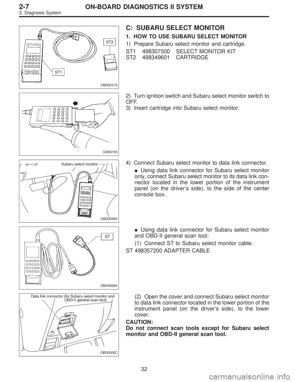
OBD0057A
C: SUBARU SELECT MONITOR
1. HOW TO USE SUBARU SELECT MONITOR
1) Prepare Subaru select monitor and cartridge.
ST1 498307500 SELECT MONITOR KIT
ST2 498349601 CARTRIDGE
G3M0150
2) Turn ignition switch and Subaru select monitor switch to
OFF.
3) Insert cartridge into Subaru select monitor.
OBD0059A
4) Connect Subaru select monitor to data link connector.
�Using data link connector for Subaru select monitor
only, connect Subaru select monitor to its data link con-
nector located in the lower portion of the instrument
panel (on the driver’s side), to the side of the center
console box.
OBD0669A
�Using data link connector for Subaru select monitor
and OBD-II general scan tool;
(1) Connect ST to Subaru select monitor cable.
ST 498357200 ADAPTER CABLE
OBD0006C
(2) Open the cover and connect Subaru select monitor
to data link connector located in the lower portion of the
instrument panel (on the driver’s side), to the lower
cover.
CAUTION:
Do not connect scan tools except for Subaru select
monitor and OBD-II general scan tool.
32
2-7ON-BOARD DIAGNOSTICS II SYSTEM
3. Diagnosis System
Page 1266 of 2248
OBD0057A
2. SUBARU SELECT MONITOR
After performing diagnostics and clearing the memory,
check for any remaining unresolved trouble data.
1) Prepare Subaru select monitor and cartridge.
ST1 498307500 SELECT MONITOR KIT
ST2 498349601 CARTRIDGE
G3M0151
2) Turn ignition switch and monitor switch to OFF.
G3M0150
3) Insert cartridge into Subaru select monitor.
OBD0005B
4) Connect test mode connector at the lower portion of
instrument panel (on the driver’s side), to the side of the
center console box.
OBD0059A
5) Connect Subaru select monitor to data link connector.
�Using data link connector for Subaru select monitor only:
Connect Subaru select monitor to its data link connector
located in the lower portion of the instrument panel (on the
driver’s side), to the side of the center console box.
60
2-7ON-BOARD DIAGNOSTICS II SYSTEM
3. Diagnosis System
Page 1268 of 2248

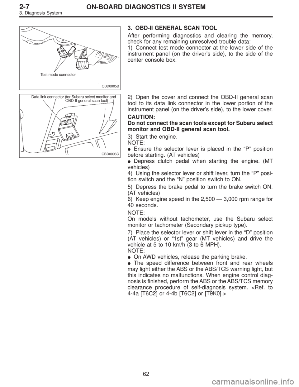
OBD0005B
3. OBD-II GENERAL SCAN TOOL
After performing diagnostics and clearing the memory,
check for any remaining unresolved trouble data:
1) Connect test mode connector at the lower side of the
instrument panel (on the driver’s side), to the side of the
center console box.
OBD0006C
2) Open the cover and connect the OBD-II general scan
tool to its data link connector in the lower portion of the
instrument panel (on the driver’s side), to the lower cover.
CAUTION:
Do not connect the scan tools except for Subaru select
monitor and OBD-II general scan tool.
3) Start the engine.
NOTE:
�Ensure the selector lever is placed in the“P”position
before starting. (AT vehicles)
�Depress clutch pedal when starting the engine. (MT
vehicles)
4) Using the selector lever or shift lever, turn the“P”posi-
tion switch and the“N”position switch to ON.
5) Depress the brake pedal to turn the brake switch ON.
(AT vehicles)
6) Keep engine speed in the 2,500—3,000 rpm range for
40 seconds.
NOTE:
On models without tachometer, use the Subaru select
monitor or tachometer (Secondary pickup type).
7) Place the selector lever or shift lever in the“D”position
(AT vehicles) or“1st”gear (MT vehicles) and drive the
vehicle at 5 to 10 km/h (3 to 6 MPH).
NOTE:
�On AWD vehicles, release the parking brake.
�The speed difference between front and rear wheels
may light either the ABS or the ABS/TCS warning light, but
this indicates no malfunctions. When engine control diag-
nosis is finished, perform the ABS or the ABS/TCS memory
clearance procedure of self-diagnosis system.
4-4a [T6C2] or 4-4b [T6C2] or [T9K0].>
62
2-7ON-BOARD DIAGNOSTICS II SYSTEM
3. Diagnosis System
Page 1270 of 2248
G3M0151
5. FINISHING DIAGNOSIS OPERATION
1) Disconnect test mode connector at the lower portion of
instrument panel (on the driver’s side), to the side of the
center console box.
2) Turn Subaru select monitor switch and ignition switch to
OFF.
3) Disconnect Subaru select monitor from its data link con-
nector.
64
2-7ON-BOARD DIAGNOSTICS II SYSTEM
3. Diagnosis System