Page 1041 of 2248
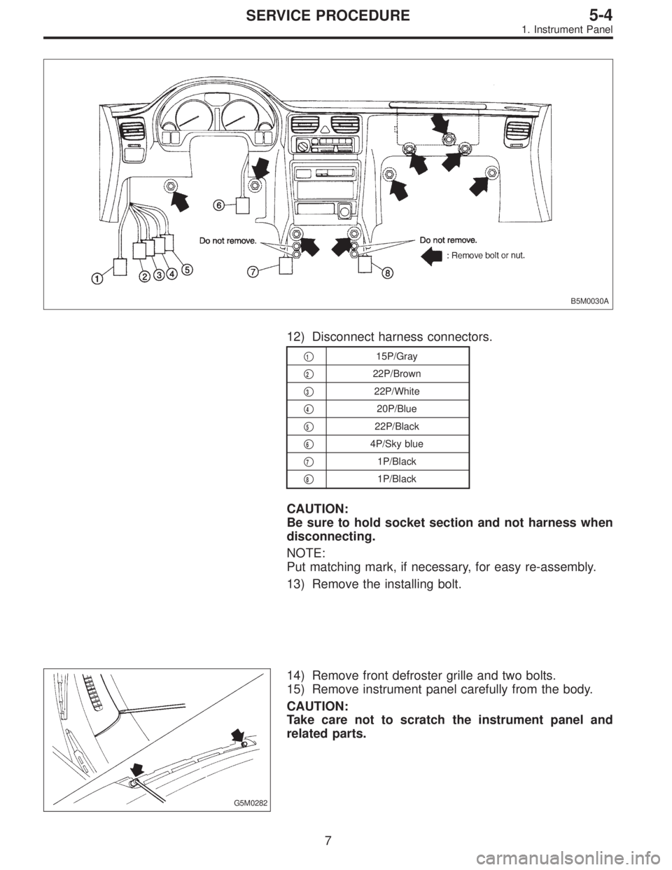
B5M0030A
12) Disconnect harness connectors.
�115P/Gray
�
222P/Brown
�
322P/White
�
420P/Blue
�
522P/Black
�
64P/Sky blue
�
71P/Black
�
81P/Black
CAUTION:
Be sure to hold socket section and not harness when
disconnecting.
NOTE:
Put matching mark, if necessary, for easy re-assembly.
13) Remove the installing bolt.
G5M0282
14) Remove front defroster grille and two bolts.
15) Remove instrument panel carefully from the body.
CAUTION:
Take care not to scratch the instrument panel and
related parts.
7
5-4SERVICE PROCEDURE
1. Instrument Panel
Page 1057 of 2248
G5M0312
3) Remove lower cover.
Disconnect airbag connector (AB3) and (AB8) below steer-
ing column.
CAUTION:
Do not reconnect airbag connector at steering column
until front sensors are securely re-installed.
G5M0313
4) Remove console box. Discon-
nect 2-pin blue connector (AB4) (right side front sensor)
and 2-pin orange connector (AB5) (left side front sensor)
from airbag control module.
G5M0314
5) Roll up floor mat and side sill cover.
[W5A10].> Remove front sensor harness from clip and pro-
tector.
6) Remove front wheels.
7) Remove front mud guard.
G5M0315
8) Remove wiring harness clips.
G5M0316
9) Remove grommet.
14
5-5SERVICE PROCEDURE
4. Front Sensor
Page 1062 of 2248
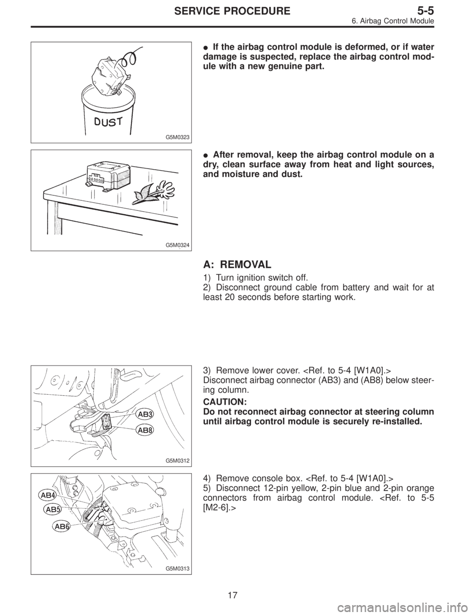
G5M0323
�If the airbag control module is deformed, or if water
damage is suspected, replace the airbag control mod-
ule with a new genuine part.
G5M0324
�After removal, keep the airbag control module on a
dry, clean surface away from heat and light sources,
and moisture and dust.
A: REMOVAL
1) Turn ignition switch off.
2) Disconnect ground cable from battery and wait for at
least 20 seconds before starting work.
G5M0312
3) Remove lower cover.
Disconnect airbag connector (AB3) and (AB8) below steer-
ing column.
CAUTION:
Do not reconnect airbag connector at steering column
until airbag control module is securely re-installed.
G5M0313
4) Remove console box.
5) Disconnect 12-pin yellow, 2-pin blue and 2-pin orange
connectors from airbag control module.
[M2-6].>
17
5-5SERVICE PROCEDURE
6. Airbag Control Module
Page 1811 of 2248
1. Electrical Components Location
B5M0395A
Connector No. (AB1) (AB2) (AB3) (AB4) (AB5) (AB6) (AB7) (AB8) (AB9) (AB10)
Pole73322123333
Color Yellow Yellow Yellow Blue Orange Yellow Yellow Yellow Yellow Yellow
Male/Female Male Female Female Female Female Female Male Male Male Female
2
5-5SUPPLEMENTAL RESTRAINT SYSTEM
1. Electrical Components Location
Page 1890 of 2248
 The sketch of each connector in the wiring diagram
usually shows the“A”side of the connector. The relation-
ship between the wire color, terminal number and connec-
tor is described in")
G6M0200
4) The sketch of each connector in the wiring diagram
usually shows the“A”side of the connector. The relation-
ship between the wire color, terminal number and connec-
tor is described in figure.
NOTE:
A wire which runs in one direction from a connector termi-
nal sometimes may have a different color from that which
runs in the other direction from that terminal.
G6M0216
5) In wiring diagram, connectors which have no terminal
number refer to one-pole types. Sketches of these connec-
tors are omitted intentionally.
G6M0201
6) The following color codes are used to indicate the col-
ors of the wires used.
Color code Color
L Blue
B Black
Y Yellow
G Green
RRed
W White
Br Brown
Lg Light green
Gr Gray
P Pink
Or Orange
Lb Light Blue
V Violet
SA Sealed (Inner)
SB Sealed (Outer)
G6M0202
7) The wire color code, which consists of two letters (or
three letters including Br or Lg), indicates the standard
color (base color of the wire covering) by its first letter and
the stripe marking by its second letter.
4
6-3WIRING DIAGRAM
1. General Description
Page 2097 of 2248

F2 3 * B-2 B100 Bulkhead wiring harness (With A.B.S. and T.C.S. mo")
�LHD model
Connector Connecting to
No. Pole Color Area No. Name
F1 20 Blue B-2 P1 Floor wiring harness (With A.B.S. and T.C.S. model)
F2 3 * B-2 B100 Bulkhead wiring harness (With A.B.S. and T.C.S. model)
F3 3 Brown B-1 Front turn signal and side marker light RH
F4 2 Black B-1 Front clearance light RH
F5 1 Black B-1 Horn
F6 2 * C-1 Front fog light RH
F7 3 Black B-1 Headlight RH
F8 2 Gray B-1
Hydraulic unit (A.B.S.)
F9 12 Black B-1
F10 4 * B-2 T.C.S. motor relay
F11 6 * B-2 T.C.S. valve relay
F12 2 Black B-2 T.C.S. pressure switch
F13 2 Black B-2 T.C.S. motor
F14 2 Gray B-2
Hydraulic unit (T.C.S.)
F15 12 Gray B-2
F16 3 Black C-1 Sub fan motor
F17 3 Black C-2 Radiator main fan motor
F18 2 Gray C-3 Front hood switch (Security)
F19 3 Brown C-3 Front turn signal and side marker light LH
F21 2 * C-2 Front fog light LH
F22 2 Black C-3 Front clearance light LH
F23 3 Black C-2 Headlight LH
F24 1 Black B-2 A/C compressor
F25 1 x 2 * B-2
Generator
F26 2 Gray B-2
F27 4 Black B-3 A/C fuse (Relay holder)
F28 4 Black B-3 A/C main fan relay-1 (Relay holder)
F29 4 Black B-3 A/C sub fan relay-2 (Relay holder)
F30 4 Black B-3 A/C main fan relay-2 (Relay holder)
F31 4 Black B-3 A/C relay (Relay holder)
F32 2 Green B-2 Front washer motor
F33 2 * B-3 Rear washer motor
F34 4 Black B-3 SBF holder
F35 8 Black B-3
M/B F36 3 * B-3
F37 2 Black B-3
F38 2 Black B-3
F39 1 Brown B-3
F40 10 Gray B-4
F/B F41 3 Gray B-4
F42 5 Gray B-4
F43 3 Orange B-4 A/C diode
F44 8 * B-3 B61
Bulkhead wiring harness
F45 20 * B-3 B62
F46 2 Black B-4 B108 Bulkhead wiring harness (Outback)
*: Non-colored
111
6-3WIRING DIAGRAM
8. Electrical Wiring Harness and Ground Point
Page 2098 of 2248
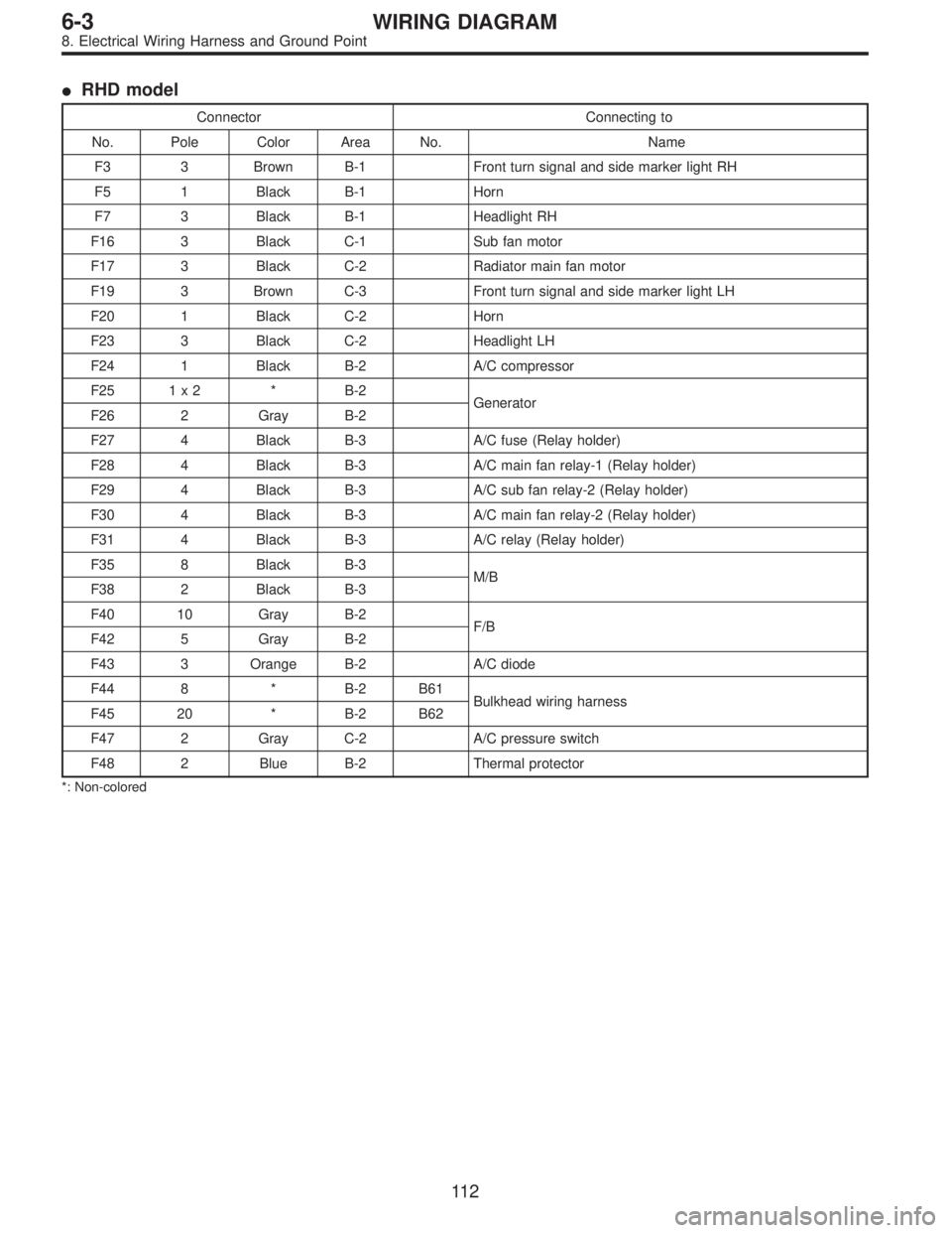
�RHD model
Connector Connecting to
No. Pole Color Area No. Name
F3 3 Brown B-1 Front turn signal and side marker light RH
F5 1 Black B-1 Horn
F7 3 Black B-1 Headlight RH
F16 3 Black C-1 Sub fan motor
F17 3 Black C-2 Radiator main fan motor
F19 3 Brown C-3 Front turn signal and side marker light LH
F20 1 Black C-2 Horn
F23 3 Black C-2 Headlight LH
F24 1 Black B-2 A/C compressor
F25 1 x 2 * B-2
Generator
F26 2 Gray B-2
F27 4 Black B-3 A/C fuse (Relay holder)
F28 4 Black B-3 A/C main fan relay-1 (Relay holder)
F29 4 Black B-3 A/C sub fan relay-2 (Relay holder)
F30 4 Black B-3 A/C main fan relay-2 (Relay holder)
F31 4 Black B-3 A/C relay (Relay holder)
F35 8 Black B-3
M/B
F38 2 Black B-3
F40 10 Gray B-2
F/B
F42 5 Gray B-2
F43 3 Orange B-2 A/C diode
F44 8 * B-2 B61
Bulkhead wiring harness
F45 20 * B-2 B62
F47 2 Gray C-2 A/C pressure switch
F48 2 Blue B-2 Thermal protector
*: Non-colored
11 2
6-3WIRING DIAGRAM
8. Electrical Wiring Harness and Ground Point
Page 2197 of 2248

F2 3 * B-2 B100 Bulkhead wiring harness (With A.B.S. and T.C.S. mo")
�LHD model
Connector Connecting to
No. Pole Color Area No. Name
F1 20 Blue B-2 P1 Floor wiring harness (With A.B.S. and T.C.S. model)
F2 3 * B-2 B100 Bulkhead wiring harness (With A.B.S. and T.C.S. model)
F3 3 Brown B-1 Front turn signal and side marker light RH
F4 2 Black B-1 Front clearance light RH
F5 1 Black B-1 Horn
F6 2 * C-1 Front fog light RH
F7 3 Black B-1 Headlight RH
F8 2 Gray B-1
Hydraulic unit (A.B.S.)
F9 12 Black B-1
F10 4 * B-2 T.C.S. motor relay
F11 6 * B-2 T.C.S. valve relay
F12 2 Black B-2 T.C.S. pressure switch
F13 2 Black B-2 T.C.S. motor
F14 2 Gray B-2
Hydraulic unit (T.C.S.)
F15 12 Gray B-2
F16 3 Black C-1 Sub fan motor
F17 3 Black C-2 Radiator main fan motor
F18 2 Gray C-3 Front hood switch (Security)
F19 3 Brown C-3 Front turn signal and side marker light LH
F21 2 * C-2 Front fog light LH
F22 2 Black C-3 Front clearance light LH
F23 3 Black C-2 Headlight LH
F24 1 Black B-2 A/C compressor
F25 1 x 2 * B-2
Generator
F26 2 Gray B-2
F27 4 Black B-3 A/C fuse (Relay holder)
F28 4 Black B-3 A/C main fan relay-1 (Relay holder)
F29 4 Black B-3 A/C sub fan relay-2 (Relay holder)
F30 4 Black B-3 A/C main fan relay-2 (Relay holder)
F31 4 Black B-3 A/C relay (Relay holder)
F32 2 Green B-2 Front washer motor
F33 2 * B-3 Rear washer motor
F34 4 Black B-3 SBF holder
F35 8 Black B-3
M/B F36 3 * B-3
F37 2 Black B-3
F38 2 Black B-3
F39 1 Brown B-3
F40 10 Gray B-4
F/B F41 3 Gray B-4
F42 5 Gray B-4
F43 3 Orange B-4 A/C diode
F44 8 * B-3 B61
Bulkhead wiring harness
F45 20 * B-3 B62
F46 2 Black B-4 B108 Bulkhead wiring harness (Outback)
*: Non-colored
111
6-3WIRING DIAGRAM
8. Electrical Wiring Harness and Ground Point
![SUBARU LEGACY 1995 Service Repair Manual G5M0312
3) Remove lower cover. <Ref. to 5-4 [W1A0].>
Disconnect airbag connector (AB3) and (AB8) below steer-
ing column.
CAUTION:
Do not reconnect airbag connector at steering column
until front sens](/manual-img/17/57432/w960_57432-1056.png "SUBARU LEGACY 1995 Service Repair Manual G5M0312
3) Remove lower cover. <Ref. to 5-4 [W1A0].>
Disconnect airbag connector (AB3) and (AB8) below steer-
ing column.
CAUTION:
Do not reconnect airbag connector at steering column
until front sens")
 (AB2) (AB3) (AB4) (AB5) (AB6) (AB7) (AB8) (AB9) (AB10)
Pole73322123333
Color Yellow Yellow Yellow Blue Orange Yellow Yellow Yellow Yellow")