Page 1139 of 2248
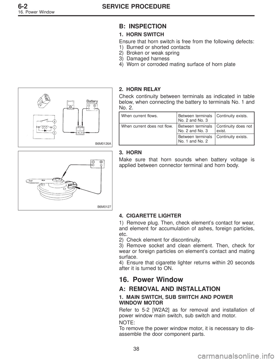
B: INSPECTION
1. HORN SWITCH
Ensure that horn switch is free from the following defects:
1) Burned or shorted contacts
2) Broken or weak spring
3) Damaged harness
4) Worn or corroded mating surface of horn plate
B6M0126A
2. HORN RELAY
Check continuity between terminals as indicated in table
below, when connecting the battery to terminals No. 1 and
No. 2.
When current flows. Between terminals
No. 2 and No. 3Continuity exists.
When current does not flow. Between terminals
No. 2 and No. 3Continuity does not
exist.
Between terminals
No. 1 and No. 2Continuity exists.
B6M0127
3. HORN
Make sure that horn sounds when battery voltage is
applied between connector terminal and horn body.
4. CIGARETTE LIGHTER
1) Remove plug. Then, check element’s contact for wear,
and element for accumulation of ashes, foreign particles,
etc.
2) Check element for discontinuity.
3) Remove socket and clean element. Then, check for
wear or foreign particles on element’s contact and mating
surface.
4) Ensure that cigarette lighter returns within 20 seconds
after it is turned to ON.
16. Power Window
A: REMOVAL AND INSTALLATION
1. MAIN SWITCH, SUB SWITCH AND POWER
WINDOW MOTOR
Refer to 5-2 [W2A2] as for removal and installation of
power window main switch, sub switch and motor.
NOTE:
To remove the power window motor, it is necessary to dis-
assemble the door component parts.
38
6-2SERVICE PROCEDURE
16. Power Window
Page 1140 of 2248
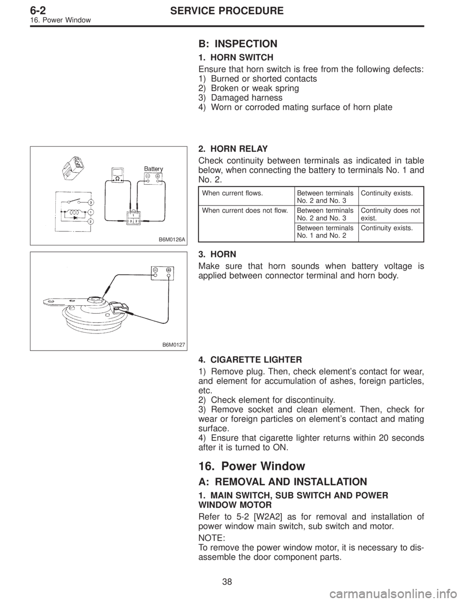
B: INSPECTION
1. HORN SWITCH
Ensure that horn switch is free from the following defects:
1) Burned or shorted contacts
2) Broken or weak spring
3) Damaged harness
4) Worn or corroded mating surface of horn plate
B6M0126A
2. HORN RELAY
Check continuity between terminals as indicated in table
below, when connecting the battery to terminals No. 1 and
No. 2.
When current flows. Between terminals
No. 2 and No. 3Continuity exists.
When current does not flow. Between terminals
No. 2 and No. 3Continuity does not
exist.
Between terminals
No. 1 and No. 2Continuity exists.
B6M0127
3. HORN
Make sure that horn sounds when battery voltage is
applied between connector terminal and horn body.
4. CIGARETTE LIGHTER
1) Remove plug. Then, check element’s contact for wear,
and element for accumulation of ashes, foreign particles,
etc.
2) Check element for discontinuity.
3) Remove socket and clean element. Then, check for
wear or foreign particles on element’s contact and mating
surface.
4) Ensure that cigarette lighter returns within 20 seconds
after it is turned to ON.
16. Power Window
A: REMOVAL AND INSTALLATION
1. MAIN SWITCH, SUB SWITCH AND POWER
WINDOW MOTOR
Refer to 5-2 [W2A2] as for removal and installation of
power window main switch, sub switch and motor.
NOTE:
To remove the power window motor, it is necessary to dis-
assemble the door component parts.
38
6-2SERVICE PROCEDURE
16. Power Window
Page 1141 of 2248
B6M0128A
B: INSPECTION
1. MAIN SWITCH
Set power window main switch to each position and check
continuity between terminals as indicated in table below:
LHD model
Window lock switchSwitch
PositionFront RH Front LH Rear RH Rear LH
7 14 9 12 7 13 8 12 7 6 11 12 7 10 5 12
NORMALUP��
��������������
OFF������������
DOWN��������
��������
LOCKUP��
��������
OFF���������
DOWN����������
RHD model
Window lock switchSwitch
PositionFront RH Front LH Rear RH Rear LH
7 11 6 12 7 10 5 12 7 9 14 12 7 13 8 12
AUTO UP��
��
UP����������������
OFF������������
DOWN��������
��������
AUTO DOWN����
39
6-2SERVICE PROCEDURE
16. Power Window
Page 1142 of 2248
B6M0129A
2. SUB SWITCH
Set power window sub switch to each position and check
continuity between terminals as indicated in table below:
Terminal
Switch position51342
UP��
��
*
OFF��
��
*
DOWN��
��
3. POWER WINDOW MOTOR
1) Make sure that power window motor rotates properly
when battery voltage is applied to terminals of motor con-
nector.
2) Change polarity of battery connections to terminals to
ensure that motor rotates in reverse direction.
B6M0130A
4. POWER WINDOW RELAY
Check continuity between terminals as indicated in table
below, when connecting the battery to terminal No. 1 and
No. 3.
When current flows. Between terminals
No. 2 and No. 4Continuity exists.
When current does not flow. Between terminals
No. 2 and No. 4Continuity does not
exist.
Between terminals
No. 1 and No. 3Continuity exists.
40
6-2SERVICE PROCEDURE
16. Power Window
Page 1163 of 2248
C: FUNCTION TEST
1. SECURITY SYSTEM OPERATION
1) Fully open all the door windows.
2) Turn the ignition switch to OFF and remove ignition key
from ignition switch.
3) Get out of the vehicle and lock the driver’s door using a
ignition key.
4) Check that the security indicator light illuminates.
5) When the security indicator light illuminates, wait for 30
seconds.
After 30 seconds, check that the light starts repeating 0.2
sec. ON and 2.4 sec. OFF sequence.
6) Unlock the driver’s door using the inside lock knob and
open the door.
Ensure that:
(1) the horn sounds and headlights flash intermittently
at 0.2 sec. ON and 0.6 sec. OFF. intervals, and
(2) the engine will not start even if the ignition switch
is turned to START.
7) Unlock the driver’s door one time using the ignition key.
Ensure the horn and headlights turn off.
8) Close and lock the driver’s door without using a ignition
key. (Set the inside lock knob to LOCK and then close the
door while lifting the outer handle).
Check that the security indicator light illuminates continu-
ously.
9) Within 30 seconds after the above step 8), unlock the
rear LH door using the inside lock knob and open the door.
Check that the security indicator light flashes at 0.5 sec.
intervals.
10) Close the rear LH door and lock the door using the
inside lock knob.
Check that the security indicator light illuminates continu-
ously.
11) Perform the above steps 9) and 10) on the rear RH
door and front RH door.
12) Within 30 seconds after above step 11) has been
finished, pull the engine hood opener lever and open the
engine hood.
Check that the security indicator light flashes at 0.5 sec.
intervals.
13) Close the engine hood completely.
Check that the security indicator light illuminates continu-
ously.
59
6-2SERVICE PROCEDURE
22. Security System
Page 1177 of 2248
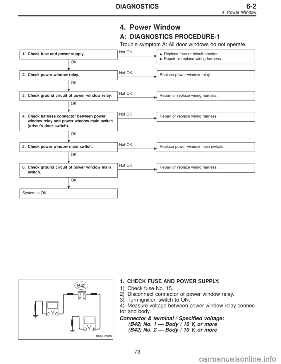
4. Power Window
A: DIAGNOSTICS PROCEDURE-1
Trouble symptom A: All door windows do not operate.
1. Check fuse and power supply.
OK
�Not OK
�Replace fuse or circuit breaker.
�Repair or replace wiring harness.
2. Check power window relay.
OK
�Not OK
Replace power window relay.
3. Check ground circuit of power window relay.
OK
�Not OK
Repair or replace wiring harness.
4. Check harness connector between power
window relay and power window main switch
(driver’s door switch).
OK
�Not OK
Repair or replace wiring harness.
5. Check power window main switch.
OK
�Not OK
Replace power window main switch.
6. Check ground circuit of power window main
switch.
OK
�Not OK
Repair or replace wiring harness.
System is OK.
B6M0390A
1. CHECK FUSE AND POWER SUPPLY.
1) Check fuse No. 15.
2) Disconnect connector of power window relay.
3) Turn ignition switch to ON.
4) Measure voltage between power window relay connec-
tor and body.
Connector & terminal / Specified voltage:
(B42) No. 1—Body / 10 V, or more
(B42) No. 2—Body / 10 V, or more
�
�
�
�
�
�
73
6-2DIAGNOSTICS
4. Power Window
Page 1178 of 2248
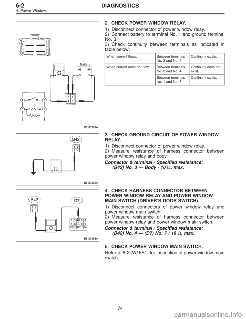
B6M0391A
2. CHECK POWER WINDOW RELAY.
1) Disconnect connector of power window relay.
2) Connect battery to terminal No. 1 and ground terminal
No. 3.
3) Check continuity between terminals as indicated in
table below:
When current flows. Between terminals
No. 2 and No. 4Continuity exists.
When current does not flow. Between terminals
No. 2 and No. 4Continuity does not
exist.
Between terminals
No. 1 and No. 3Continuity exists.
B6M0392A
3. CHECK GROUND CIRCUIT OF POWER WINDOW
RELAY.
1) Disconnect connector of power window relay.
2) Measure resistance of harness connector between
power window relay and body.
Connector & terminal / Specified resistance:
(B42) No. 3—Body / 10Ω, max.
B6M0393A
4. CHECK HARNESS CONNECTOR BETWEEN
POWER WINDOW RELAY AND POWER WINDOW
MAIN SWITCH (DRIVER’S DOOR SWITCH).
1) Disconnect connectors of power window relay and
power window main switch.
2) Measure resistance of harness connector between
power window relay and power window main switch.
Connector & terminal / Specified resistance:
(B42) No. 4—(D7) No.7/10Ω, max.
5. CHECK POWER WINDOW MAIN SWITCH.
Refer to 6-2 [W16B1] for inspection of power window main
switch.
74
6-2DIAGNOSTICS
4. Power Window
Page 1179 of 2248
B6M0394A
6. CHECK GROUND CIRCUIT OF POWER WINDOW
MAIN SWITCH.
1) Disconnect connector of power window main switch.
2) Measure resistance of harness connector between
power window main switch and body.
Connector & terminal / Specified resistance:
(D7) No. 12—Body / 10Ω, max.
75
6-2DIAGNOSTICS
4. Power Window