Page 101 of 2248

1. Lubrication System
A: SPECIFICATIONS
Lubrication methodForced lubrication
Oil pumpPump typeTrochoid type
Number of teethInner rotor 9
Outer rotor 10
Outer rotor diameter x thickness 78x9mm(3.07 x 0.35 in)
Tip clearance between inner and outer rotorSTANDARD 0.04 — 0.14 mm (0.0016 — 0.0055 in)
LIMIT 0.18 mm (0.0071 in)
Side clearance between inner rotor and pump
caseSTANDARD 0.02 — 0.07 mm (0.0008 — 0.0028 in)
LIMIT 0.15 mm (0.0059 in)
Case clearance between outer rotor and pump
caseSTANDARD 0.10 — 0.175 mm (0.0039 — 0.0069 in)
LIMIT 0.20 mm (0.0079 in)
Capacity at
80°C (176°F)700 rpm Discharge- pressure 98 kPa (1.0 kg/cm
2, 14 psi) or more
- quantity 4.2�(4.4 US qt, 3.7 Imp qt)/min.
5,000 rpm Discharge- pressure 294 kPa (3.0 kg/cm
2, 43 psi) or more
- quantity 42.0�(11.10 US gal, 9.24 Imp gal)/min.
Relief valve operation pressure 490 kPa (5.0 kg/cm
2, 71 psi)
Oil filterTypeFull-flow filter type
Filtration area 1,000 cm
2(155 sq in)
By-pass valve opening pressure 157 kPa (1.6 kg/cm
2, 23 psi)
Outer diameter x width 80 x 70 mm (3.15 x 2.76 in)
Oil filter to engine thread size M 20 x 1.5
Relief valve (on rocker shaft) operation pressure 69 kPa (0.7kg/cm
2, 10 psi)
Oil pressure
switchTypeImmersed contact point type
Working voltage — wattage 12 V — 3.4 W or less
Warning light activation pressure 14.7 kPa (0.15 kg/cm
2, 2.1 psi)
Proof pressure More than 981 kPa (10 kg/cm
2, 142 psi)
Oil pan capacity4.0�(4.2 US qt, 3.5 Imp qt)
2
2-4SPECIFICATIONS AND SERVICE DATA
1. Lubrication System
Page 277 of 2248
1. Manual Transmission and
Differential
A: SPECIFICATIONS
ItemModel
FWD AWD
2200 cc 2200 cc
Type 5-forward speeds with synchromesh and 1-reverse
Transmission gear ratio1st 3.545
2nd 2.111
3rd 1.448
4th 1.088
5th 0.825 0.780
Reverse 3.416
Front reduction
gearFinalType of gear Hypoid
Gear ratio 3.454 3.900
Rear reduction
gearTransferType of gear — Helical
Gear ratio — 1.000
FinalType of gear — Hypoid
Gear ratio — 3.900
Front
differentialType and number of gear Straight bevel gear (Bevel pinion: 2, Bevel gear: 2)
Center
differentialType and number of gear —Straight bevel gear
(Bevel pinion: 2, Bevel gear: 2 and
viscous coupling)
Transmission gear oil GL-5
Transmission oil capacity 3.3�(3.5 US qt, 2.9 Imp qt) 4.0�(4.2 US qt, 3.5 Imp qt)
2
3-1SPECIFICATIONS AND SERVICE DATA
1. Manual Transmission and Differential
Page 347 of 2248

Automatic
transmis-
sionOil pumpType Variable-capacity type vane pump
Driving method Driven by engine
Number of vanes 9 pieces
Hydraulic
controlTypeElectronic/hydraulic control
[Four forward speed changes by electrical signals
of car speed and accelerator (throttle) opening]
Fluid Dexron II type Automatic transmission fluid
Fluid capacity 7.9�(8.4 US qt, 7.0 Imp qt)
LubricationLubrication system Forced feed lubrication with oil pump
Oil Automatic transmission fluid (above mentioned.)
Cooling Cooling system Liquid-cooled cooler incorporated in radiator
HarnessInhibitor switch 12 poles
Transmission harness polesFWD ... 11
AWD ... 13
TransferTransfer clutch Hydraulic multi-plate clutch
Control method Electronic, hydraulic type
LubricantThe same Automatic Transmission Fluid used in
automatic transmission.
1st reduction gear ratio 1.000 (53/53)
Final
reductionFinal gear
ratioFront driveFWD 3.900 (39/10)
AWD 4.111 (37/9)
Speedometer gear ratio 0.83 (19/23)
Lubrication oil API, GL-5
Oil
capacityFront drive 1.2�(1.3 US qt, 1.1 Imp qt)
AT F
cooling
systemRadiation capacity 1.651 kW (1,420 kcal/h, 5,635 BTU/h)
3
3-2SPECIFICATIONS AND SERVICE DATA
1. Automatic Transmission and Differential
Page 426 of 2248
 Tighten the drain plugs.
Tightening torque:
Diff.
44±3 N⋅m (4.5±0.3 kg-m, 32.5±2.2 ft-lb)
AT F
25±2 N⋅m (2.5±0.2 kg-m, 18.1±1.4 ft-lb)
G3M0437
11) Insert the input shaft while tu")
G3M0325
10) Tighten the drain plugs.
Tightening torque:
Diff.
44±3 N⋅m (4.5±0.3 kg-m, 32.5±2.2 ft-lb)
AT F
25±2 N⋅m (2.5±0.2 kg-m, 18.1±1.4 ft-lb)
G3M0437
11) Insert the input shaft while turning lightly by hand.
CAUTION:
Be careful not to damage the bushing.
G3M0327
12) Install the torque converter clutch assembly.
(1) Install the oil pump shaft to the torque converter
clutch.
NOTE:
Make sure the clip fits securely in its groove.
(2) Holding the torque converter clutch assembly by
hand, carefully install it to the torque converter clutch
case. Be careful not to damage the bushing. Also avoid
undue contact between the oil pump shaft bushing and
stator shaft portion of the oil pump cover.
(3) Rotate the shaft lightly by hand to engage the
splines securely.
13) Fill ATF and differential gear oil.
Oil capacity:
Diff.
1.1—1.3�(1.2—1.4 US qt, 1.0—1.1 Imp qt)
AT F
7.9—8.2�(8.4—8.7 US qt, 7.0—7.2 Imp qt)
NOTE:
After filling oil, insert the oil level gauge into the oil inlet.
82
3-2SERVICE PROCEDURE
4. Overall Transmission
Page 478 of 2248
1. AWD System
A: SPECIFICATIONS
1. REAR FINAL REDUCTION GEAR RATIO
Type of gearHypoid
MT AT
2200 cc 2200 cc
Gear ratio (Number of
gear teeth)3.900
(39/10)4 . 111
(37/9)
Oil capacity 0.8�(0.8 US qt, 0.7 Imp qt)
Rear differential gear
oilGL-5
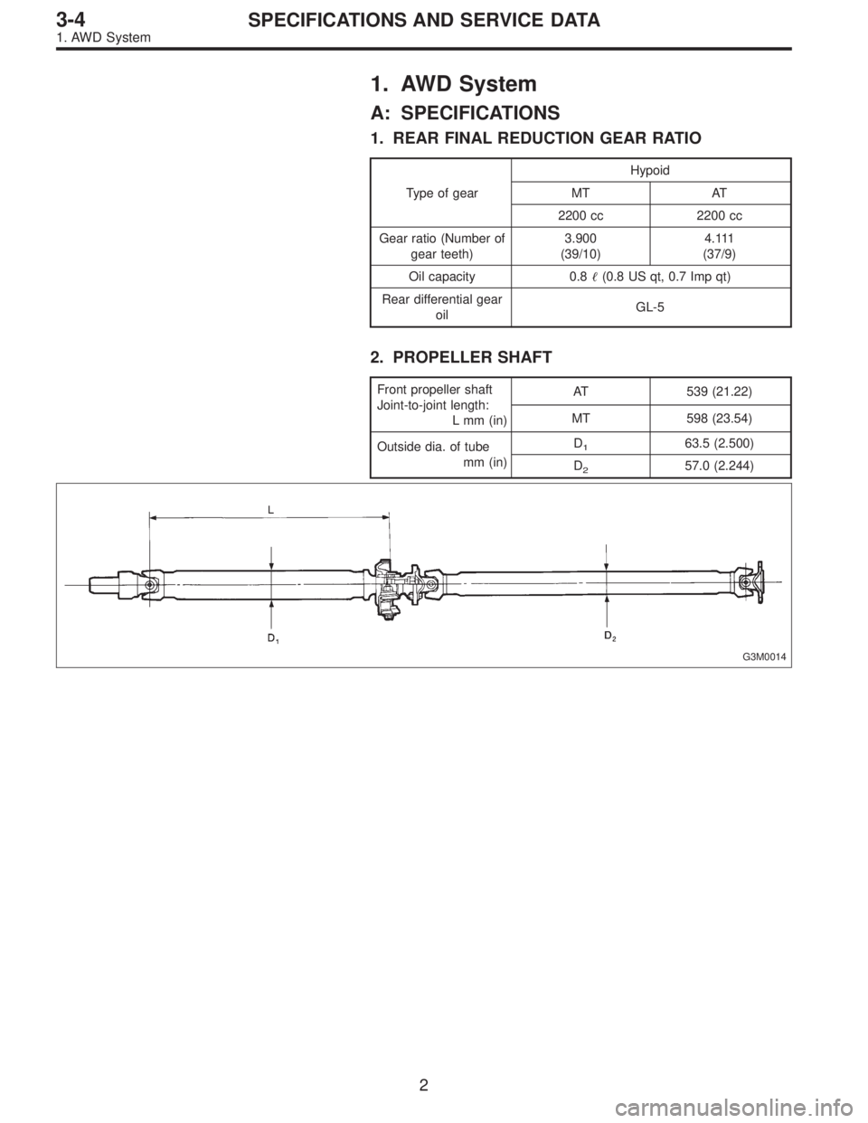
2. PROPELLER SHAFT
Front propeller shaft
Joint-to-joint length:
L mm (in)AT 539 (21.22)
MT 598 (23.54)
Outside dia. of tube
mm (in)D
163.5 (2.500)
D
257.0 (2.244)
G3M0014
2
3-4SPECIFICATIONS AND SERVICE DATA
1. AWD System
Page 481 of 2248

383505200 3.12 mm (0.1228 in)
383515200 3.15 mm (0.1240 in)
383525200 3.18 mm (0.1252 in)
383535200 3.21 mm (0.12")
Pinion height adjusting shim thicknessPart No. Thickness
383495200 3.09 mm (0.1217 in)
383505200 3.12 mm (0.1228 in)
383515200 3.15 mm (0.1240 in)
383525200 3.18 mm (0.1252 in)
383535200 3.21 mm (0.1264 in)
383545200 3.24 mm (0.1276 in)
383555200 3.27 mm (0.1287 in)
383565200 3.30 mm (0.1299 in)
383575200 3.33 mm (0.1311 in)
383585200 3.36 mm (0.1323 in)
383595200 3.39 mm (0.1335 in)
383605200 3.42 mm (0.1346 in)
383615200 3.45 mm (0.1358 in)
383625200 3.48 mm (0.1370 in)
383635200 3.51 mm (0.1382 in)
383645200 3.54 mm (0.1394 in)
383655200 3.57 mm (0.1406 in)
383665200 3.60 mm (0.1417 in)
383675200 3.63 mm (0.1429 in)
383685200 3.66 mm (0.1441 in)
Side bearing standard width—20.00 mm (0.7874 in)
Side bearing retainer shim thicknessPart No. Thickness
383475201 0.20 mm (0.0079 in)
383475202 0.25 mm (0.0098 in)
383475203 0.30 mm (0.0118 in)
383475204 0.40 mm (0.0157 in)
383475205 0.50 mm (0.0197 in)
Crown gear to drive pinion backlash
Limit0.10—0.20 mm (0.0039—0.0079 in)
Crown gear runout on its back surface 0.05 mm (0.0020 in)
Oil capacity0.8�(0.8 US qt, 0.7 Imp qt)
5
3-4SPECIFICATIONS AND SERVICE DATA
1. AWD System
Page 513 of 2248
 Install rear cover and tighten bolts to specified torque.
Tightening torque:
29±5 N⋅m (3.0±0.5 kg-m, 21.7±3.6 ft-lb)
F: INSTALLATION
To install, reverse the removal sequence.
1) Insta")
G3M1050
19) Install rear cover and tighten bolts to specified torque.
Tightening torque:
29±5 N⋅m (3.0±0.5 kg-m, 21.7±3.6 ft-lb)
F: INSTALLATION
To install, reverse the removal sequence.
1) Install the air breather cap tapping with a plastic ham-
mer.
CAUTION:
Be sure to install new air breather cap.
2) Position front member on body by passing it under park-
ing brake cable and securing to rear differential.
NOTE:
When installing rear differential front member, do not con-
fuse the installation sequence of the upper and lower stop-
pers.
G3M1026
3) Install DOJ of rear drive shaft into rear differential.
to 3-4 [W2A2].>
ST 28099PA090 SIDE OIL SEAL PROTECTOR
G3M1051
4) Installing procedure hereafter is in the reverse order of
removal.
5) After installation, fill differential carrier with gear oil to
the upper plug level.
CAUTION:
Apply fluid packing to plug.
Fluid packing:
THREE BOND 1205 or equivalent
Oil capacity:
0.8�(0.8 US qt, 0.7 Imp qt)
Tightening torque:
44±4 N⋅m (4.5±0.4 kg-m, 32.5±2.9 ft-lb)
37
3-4SERVICE PROCEDURE
2. Rear Differential
Page 617 of 2248
1. Steering System
A: SPECIFICATIONS
Whole systemMinimum turning radius m (ft) 5.3 (17.4)
Steering angle (Inside-Outside) 37.6°—32.6°
Steering wheel diameter mm (in) 385 (15.16)
Overall gear ratio (Turns, lock to lock) 16.5 (3.2)
GearboxType Rack and pinion, Integral
Backlash 0 (Automatically adjustable)
Valve (Power steering system) Rotary valve
Pump (Power steering
system)Type Vane pump
Oil tank Installed on pump
Output cm
3(cu in)/rev. 7.2 (0.439)
Relief pressure kPa (kg/cm
2, psi) 7,355 (75, 1,067)
Hydraulic fluid controlDropping in response to increased engine
revolutions
Hydraulic fluid�(US qt, Imp qt)1,000 rpm: 7 (7.4, 6.2)
3,000 rpm: 5 (5.3, 4.4)
Range of revolution rpm 500—7,500
Revolving direction Clockwise
Working fluid (Power
steering system)Name ATF DEXRON II or IIE
Capacity Oil tank�(US qt, Imp qt)
Total0.35 (0.4, 0.3)
0.7 (0.7, 0.6)
2
4-3SPECIFICATIONS AND SERVICE DATA
1. Steering System

 5.3 (17.4)
Steering angle (Inside-Outside) 37.6°—32.6°
Steering wheel diameter mm (in) 385 (15.16)
Overall gear ratio")