Page 903 of 2248
G4M0649
17. Relay and Fuse
A: LOCATION
Relays used with A/C system are located as shown in fig-
ure.
1) A/C relay
2) Main fan (radiator fan) relay
3) Sub fan (condenser fan) relay
4) Sub fan (condenser fan) water temperature relay
5) Fuses (10 A and 20 A)
G4M0651
B: INSPECTION
1) Check conduction with a circuit tester (ohm range)
according to the following table in figure.
B4M0105A
2) Replace relays which do not meet specifications.
41
4-7SERVICE PROCEDURE
17. Relay and Fuse
Page 1538 of 2248
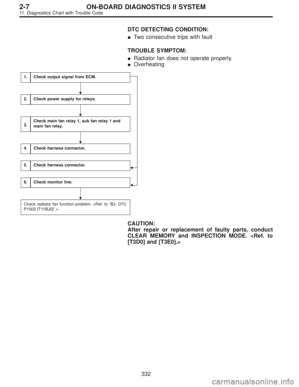
DTC DETECTING CONDITION:
�Two consecutive trips with fault
TROUBLE SYMPTOM:
�Radiator fan does not operate properly.
�Overheating
1.Check output signal from ECM.
�
�
2.Check power supply for relays.
3.Check main fan relay 1, sub fan relay 1 and
main fan relay.
4.Check harness connector.
5.Check harness connector.
6.Check monitor line.
Check radiator fan function problem.
P1502 [T11BJ0]”.>
CAUTION:
After repair or replacement of faulty parts, conduct
CLEAR MEMORY and INSPECTION MODE.
[T3D0] and [T3E0].>
�
�
�
�
332
2-7ON-BOARD DIAGNOSTICS II SYSTEM
11. Diagnostics Chart with Trouble Code
Page 1540 of 2248
OBD0736A
1
CHECK OUTPUT SIGNAL FROM ECM.
1) Turn ignition switch to OFF.
2) Connect test mode connector at the lower portion of
instrument panel (on the driver’s side), to the side of the
center console box.
3) Turn ignition switch to ON.
OBD0674A
4) Measure voltage between ECM and body.
: Connector & terminal
(B84) No. 77—Body/10 V, or more and 1 V
or less at every 2 seconds
: Go to step 6.
: Go to next.
OBD0534A
: Connector & terminal
(B84) No. 88—Body/10 V, or more
: Go to step 5.
: Go to step 2.
2
CHECK POWER SUPPLY FOR RELAYS.
Turn ignition switch to OFF.
: Is the fuse in power supply circuit broken?
: Replace the fuse.
: Go to step 3.
OBD0535
3CHECK MAIN FAN RELAY 1, SUB FAN RELAY
1 AND MAIN FAN RELAY.
1) Remove main fan relay 1. (With A/C models only)
2) Measure resistance between main fan relay 1 termi-
nals.
: Terminal
No. 1—No. 3/97±10Ω
: Go to next step.
: Replace main fan relay 1.
334
2-7ON-BOARD DIAGNOSTICS II SYSTEM
11. Diagnostics Chart with Trouble Code
Page 1892 of 2248
10) Relays are classified as normally-open or normally-
closed.
The normally-closed relay has one or more contacts.
The wiring diagram shows the relay mode when the ener-
gizing circuit is OFF.
G6M0204
Key to symbols:
�→: Current flows.
X→: Current does not flow.
6
6-3WIRING DIAGRAM
1. General Description
Page 1898 of 2248
G6M0213
5) Some connectors are provided with a lock. One type of
such a connector is disconnected by pushing the lock, and
the other, by moving the lock up. In either type the lock
shape must be identified before attempting to disconnect
the connector.
To connect, insert the connector until it snaps and confirm
that it is tightly connected.
G6M0214
6) When checking continuity between connector terminals,
or measuring voltage across the terminal and ground,
always contact tester probe(s) on terminals from the wiring
connection side. If the probe is too thick to gain access to
the terminal, use“mini”test leads.
To check water-proof connectors (which are not accessible
from the wiring side), contact test probes on the terminal
side being careful not to bend or damage the terminals.
7) Sensors, relays, electrical unit, etc., are sensitive to
strong impacts.
Handle them with care so that they are not dropped or
mishandled.
12
6-3WIRING DIAGRAM
3. Working Precautions
Page 1998 of 2248
G6M0213
5) Some connectors are provided with a lock. One type of
such a connector is disconnected by pushing the lock, and
the other, by moving the lock up. In either type the lock
shape must be identified before attempting to disconnect
the connector.
To connect, insert the connector until it snaps and confirm
that it is tightly connected.
G6M0214
6) When checking continuity between connector terminals,
or measuring voltage across the terminal and ground,
always contact tester probe(s) on terminals from the wiring
connection side. If the probe is too thick to gain access to
the terminal, use“mini”test leads.
To check water-proof connectors (which are not accessible
from the wiring side), contact test probes on the terminal
side being careful not to bend or damage the terminals.
7) Sensors, relays, electrical unit, etc., are sensitive to
strong impacts.
Handle them with care so that they are not dropped or
mishandled.
12
6-3WIRING DIAGRAM
3. Working Precautions
 A/C relay
2) Main fan (radiator fan) relay
3) Sub fan (condenser fan) relay
4) Sub fan (condense")
 Turn ignition switch to OFF.
2) Connect test mode connector at the lower portion of
instrument panel (on the driver’s side), to the side of the
center con")
 Relays are classified as normally-open or normally-
closed.
The normally-closed relay has one or more contacts.
The wiring diagram shows the relay mode when the ener-
gizing circuit is OFF.
G6M020")
 Some connectors are provided with a lock. One type of
such a connector is disconnected by pushing the lock, and
the other, by moving the lock up. In either type the lock
shape must be ident")
 Some connectors are provided with a lock. One type of
such a connector is disconnected by pushing the lock, and
the other, by moving the lock up. In either type the lock
shape must be ident")