Page 20 of 2248
G2M0093
4) Connect oil pressure gauge hose to cylinder block.
5) Start the engine, and measure oil pressure.
Oil pressure:
98 kPa (1.0 kg/cm
2,14 psi) or more at 800 rpm
294 kPa (3.0 kg/cm2, 43 psi) or more at 5,000 rpm
CAUTION:
�If oil pressure is out of specification, check oil
pump, oil filter and lubrication line.
�If oil pressure warning light is turned ON and oil
pressure is in specification, replace oil pressure
switch.
NOTE:
The specified data is based on an engine oil temperature
of 80°C (176°F).
6) After measuring oil pressure, install oil pressure switch.
Tightening torque:
25±3 N⋅m (2.5±0.3 kg-m, 18.1±2.2 ft-lb)
7) Install generator and V-belt in the reverse order of
removal, and adjust the V-belt deflection.
8
2-2
6. Engine Oil Pressure
Page 47 of 2248
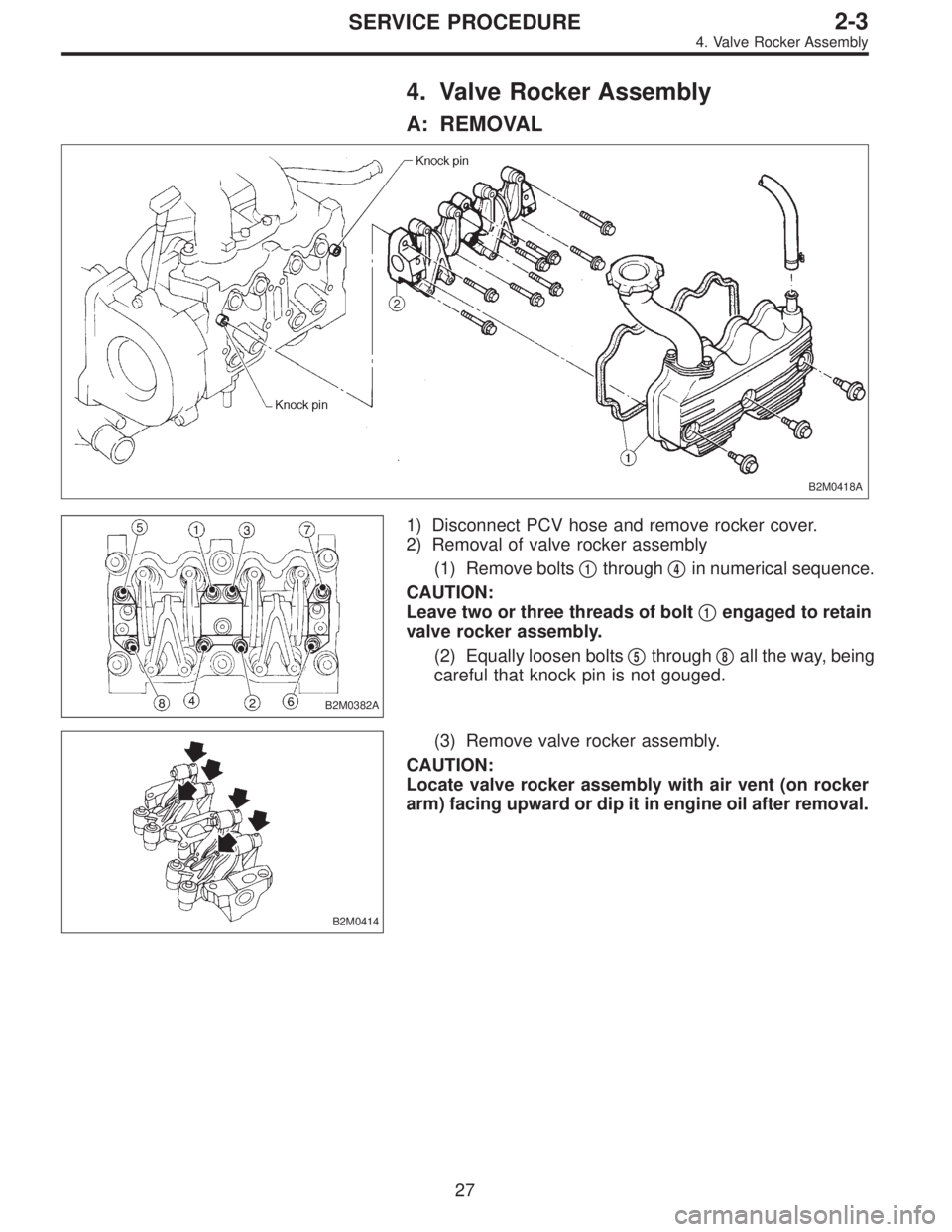
4. Valve Rocker Assembly
A: REMOVAL
B2M0418A
B2M0382A
1) Disconnect PCV hose and remove rocker cover.
2) Removal of valve rocker assembly
(1) Remove bolts�
1through�4in numerical sequence.
CAUTION:
Leave two or three threads of bolt�
1engaged to retain
valve rocker assembly.
(2) Equally loosen bolts�
5through�8all the way, being
careful that knock pin is not gouged.
B2M0414
(3) Remove valve rocker assembly.
CAUTION:
Locate valve rocker assembly with air vent (on rocker
arm) facing upward or dip it in engine oil after removal.
27
2-3SERVICE PROCEDURE
4. Valve Rocker Assembly
Page 48 of 2248
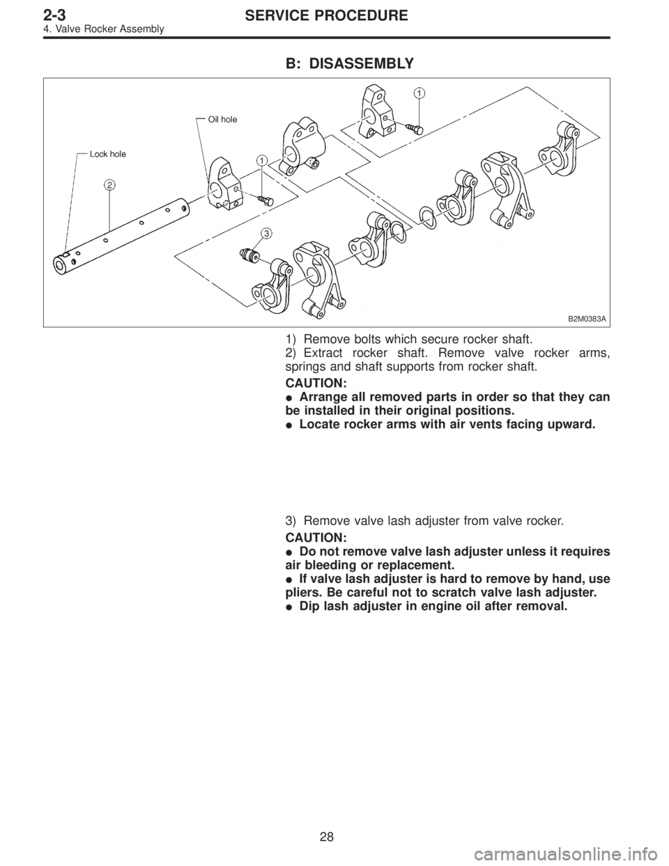
B: DISASSEMBLY
B2M0383A
1) Remove bolts which secure rocker shaft.
2) Extract rocker shaft. Remove valve rocker arms,
springs and shaft supports from rocker shaft.
CAUTION:
�Arrange all removed parts in order so that they can
be installed in their original positions.
�Locate rocker arms with air vents facing upward.
3) Remove valve lash adjuster from valve rocker.
CAUTION:
�Do not remove valve lash adjuster unless it requires
air bleeding or replacement.
�If valve lash adjuster is hard to remove by hand, use
pliers. Be careful not to scratch valve lash adjuster.
�Dip lash adjuster in engine oil after removal.
28
2-3SERVICE PROCEDURE
4. Valve Rocker Assembly
Page 58 of 2248
3. RELATED PARTS
1) Install valve rocker assembly.
B2M0418B
Tightening torque: N⋅m (kg-m, ft-lb)
T1: 5±1 (0.5±0.1, 3.6±0.7)
T2: 12±1 (1.2±0.1, 8.7±0.7)
2) Install timing belt, camshaft sprockets and related parts.
6. Cylinder Head
A: REMOVAL
1. INTAKE MANIFOLD
1) Release fuel pressure.
2) Drain engine coolant.
3) Remove intake manifold.
4) Remove engine coolant pipe.
38
2-3SERVICE PROCEDURE
5. Camshaft - 6. Cylinder Head
Page 59 of 2248
3. RELATED PARTS
1) Install valve rocker assembly.
B2M0418B
Tightening torque: N⋅m (kg-m, ft-lb)
T1: 5±1 (0.5±0.1, 3.6±0.7)
T2: 12±1 (1.2±0.1, 8.7±0.7)
2) Install timing belt, camshaft sprockets and related parts.
6. Cylinder Head
A: REMOVAL
1. INTAKE MANIFOLD
1) Release fuel pressure.
2) Drain engine coolant.
3) Remove intake manifold.
4) Remove engine coolant pipe.
38
2-3SERVICE PROCEDURE
5. Camshaft - 6. Cylinder Head
Page 71 of 2248
7. Cylinder Block
A: REMOVAL
1. RELATED PARTS
1) Remove timing belt, camshaft sprocket and related
parts.
2) Remove intake manifold and cylinder head.
2. OIL PUMP AND ENGINE COOLANT PUMP
B2M0124A
50
2-3SERVICE PROCEDURE
7. Cylinder Block
Page 103 of 2248
G2M0066
1. Oil Pump
A: REMOVAL
1) Drain engine oil.
Set container under the vehicle, and remove drain plug
from oil pan.
B2M0051A
2) Drain coolant.
Set container under the vehicle, and remove drain cock
from radiator.
B2M0302
3) Remove belt covers, timing belt and related parts.
B2M0303
4) Remove belt tensioner bracket.
G2M0210
5) Remove left cam sprocket and left belt cover No. 2.
6) Remove water pump.
4
2-4SERVICE PROCEDURE
1. Oil Pump
Page 107 of 2248
G2M0544
2. Oil Pan and Oil Strainer
A: REMOVAL
1) Remove front wheels.
2) Remove air intake duct.
3) Disconnect connector from front oxygen sensor.
G2M0295
4) Remove pitching stopper.
B2M0320
5) Remove radiator upper brackets.
B2M0053
6) Support engine with a lifting device and wire ropes.
7) Lift-up the vehicle.
CAUTION:
At this time, raise up wire ropes.
G2M0066
8) Drain engine oil.
Set container under the vehicle, and remove drain plug
from oil pan.
8
2-4SERVICE PROCEDURE
2. Oil Pan and Oil Strainer
 Connect oil pressure gauge hose to cylinder block.
5) Start the engine, and measure oil pressure.
Oil pressure:
98 kPa (1.0 kg/cm
2,14 psi) or more at 800 rpm
294 kPa (3.0 kg/cm2, 43 psi) o")
![SUBARU LEGACY 1995 Service Repair Manual 3. RELATED PARTS
1) Install valve rocker assembly.
<Ref. to 2-3 [W4E0].>
B2M0418B
Tightening torque: N⋅m (kg-m, ft-lb)
T1: 5±1 (0.5±0.1, 3.6±0.7)
T2: 12±1 (1.2±0.1, 8.7±0.7)
2) Install timing](/manual-img/17/57432/w960_57432-57.png "SUBARU LEGACY 1995 Service Repair Manual 3. RELATED PARTS
1) Install valve rocker assembly.
<Ref. to 2-3 [W4E0].>
B2M0418B
Tightening torque: N⋅m (kg-m, ft-lb)
T1: 5±1 (0.5±0.1, 3.6±0.7)
T2: 12±1 (1.2±0.1, 8.7±0.7)
2) Install timing")
![SUBARU LEGACY 1995 Service Repair Manual 3. RELATED PARTS
1) Install valve rocker assembly.
<Ref. to 2-3 [W4E0].>
B2M0418B
Tightening torque: N⋅m (kg-m, ft-lb)
T1: 5±1 (0.5±0.1, 3.6±0.7)
T2: 12±1 (1.2±0.1, 8.7±0.7)
2) Install timing](/manual-img/17/57432/w960_57432-58.png "SUBARU LEGACY 1995 Service Repair Manual 3. RELATED PARTS
1) Install valve rocker assembly.
<Ref. to 2-3 [W4E0].>
B2M0418B
Tightening torque: N⋅m (kg-m, ft-lb)
T1: 5±1 (0.5±0.1, 3.6±0.7)
T2: 12±1 (1.2±0.1, 8.7±0.7)
2) Install timing")
![SUBARU LEGACY 1995 Service Repair Manual 7. Cylinder Block
A: REMOVAL
1. RELATED PARTS
1) Remove timing belt, camshaft sprocket and related
parts.
<Ref. to 2-3 [W3A1].>
2) Remove intake manifold and cylinder head.
<Ref. to 2-3 [W6A0].>
2. OI](/manual-img/17/57432/w960_57432-70.png "SUBARU LEGACY 1995 Service Repair Manual 7. Cylinder Block
A: REMOVAL
1. RELATED PARTS
1) Remove timing belt, camshaft sprocket and related
parts.
<Ref. to 2-3 [W3A1].>
2) Remove intake manifold and cylinder head.
<Ref. to 2-3 [W6A0].>
2. OI")
 Drain engine oil.
Set container under the vehicle, and remove drain plug
from oil pan.
B2M0051A
2) Drain coolant.
Set container under the vehicle, and remove drain co")
 Remove front wheels.
2) Remove air intake duct.
3) Disconnect connector from front oxygen sensor.
G2M0295
4) Remove pitching stopper.
B2M0320
5) Remov")