Page 766 of 2248
 Drain brake fluid from reservoir of master cylinder.
2) Remove adjusting nut and cable clamp, and disconnect
PHV cable from cable bracket on engine.
3) Detach PHV")
G4M0428
8. Hill Holder
A: REMOVAL
1) Drain brake fluid from reservoir of master cylinder.
2) Remove adjusting nut and cable clamp, and disconnect
PHV cable from cable bracket on engine.
3) Detach PHV cable from clips.
4) Remove cable clamp, and disconnect PHV cable from
PHV stay.
CAUTION:
Carefully protect boots and inner cable from damage
when disconnecting PHV cable.
5) Disconnect brake pipes from PHV.
CAUTION:
�Pay attention not to drop brake fluid onto body
painting since it may dissolve paint.
�Pay attention not to damage hexagonal head of flare
nut by using pipe wrench without fail.
6) Detach PHV along with support from side frame.
CAUTION:
Exercise utmost care to prevent foreign matter from
entering into PHV when removing it.
B: INSPECTION
Check up removed parts as follows, and replace defective
ones.
1) Check if boots of PHV cable are damaged or degraded,
and if inner cable is damaged or corroded.
2) Check if return spring is worn out, damaged or cor-
roded.
3) Confirm that rolling sound of ball is heard with PHV
inclined and lever rotates smoothly.
CAUTION:
Never disassemble PHV. Replace entire PHV assembly
if necessary.
50
4-4SERVICE PROCEDURE
8. Hill Holder
Page 777 of 2248
14. ABS Sensor
A: REMOVAL
1. FRONT ABS SENSOR
1) Disconnect front ABS sensor connector located in
engine compartment.
B4M0079A
2) Remove bolts which secure sensor harness to strut.
G4M0451
3) Remove bolts which secure sensor harness to body.
G4M0443
4) Remove bolts which secure front ABS sensor to
housing, and remove front ABS sensor.
CAUTION:
�Be careful not to damage pole piece located at tip of
the sensor and teeth faces during removal.
�Do not pull sensor harness during removal.
5) Remove front disc brake caliper and disc rotor from
housing after removing front tire.
6) Remove front drive shaft and housing and hub assem-
bly.
60
4-4SERVICE PROCEDURE
14. ABS Sensor
Page 783 of 2248

15. Hydraulic Unit for ABS System
B4M0069A
�1Connector
�
2Cap
�
3Motor relay
�
4Valve relay
�
5Hydraulic control unit
�
6Front-RH outlet
�
7Rear-LH outlet�
8Rear-RH outlet
�
9Front-LH outlet
�
10Primary inlet
�
11Secondary inlet
�
12Bracket
Tightening torque: N⋅m (kg-m, ft-lb)
T1: 1.2±0.2
(0.125±0.025, 0.9±0.2)
T2: 18±5 (1.8±0.5, 13.0±3.6)
T3: 29±7 (3.0±0.7, 21.7±5.1)
T4: 32±10 (3.3±1.0, 24±7)
A: REMOVAL
1) Remove air intake duct.
2) Remove canister from engine compartment to facilitate
removal of hydraulic unit.
3) Disconnect brake pipes from hydraulic unit and plug
open joints to prevent entry of foreign particles.
G4M0455
4) Remove nuts and bolts which secure hydraulic unit, and
remove hydraulic unit from engine compartment.
CAUTION:
�Hydraulic unit cannot be disassembled. Do not
attempt to loosen bolts and nuts.
�Do not drop or bump hydraulic unit.
�Do not turn the hydraulic unit upside down or place
it on its side.
66
4-4SERVICE PROCEDURE
15. Hydraulic Unit for ABS System
Page 804 of 2248
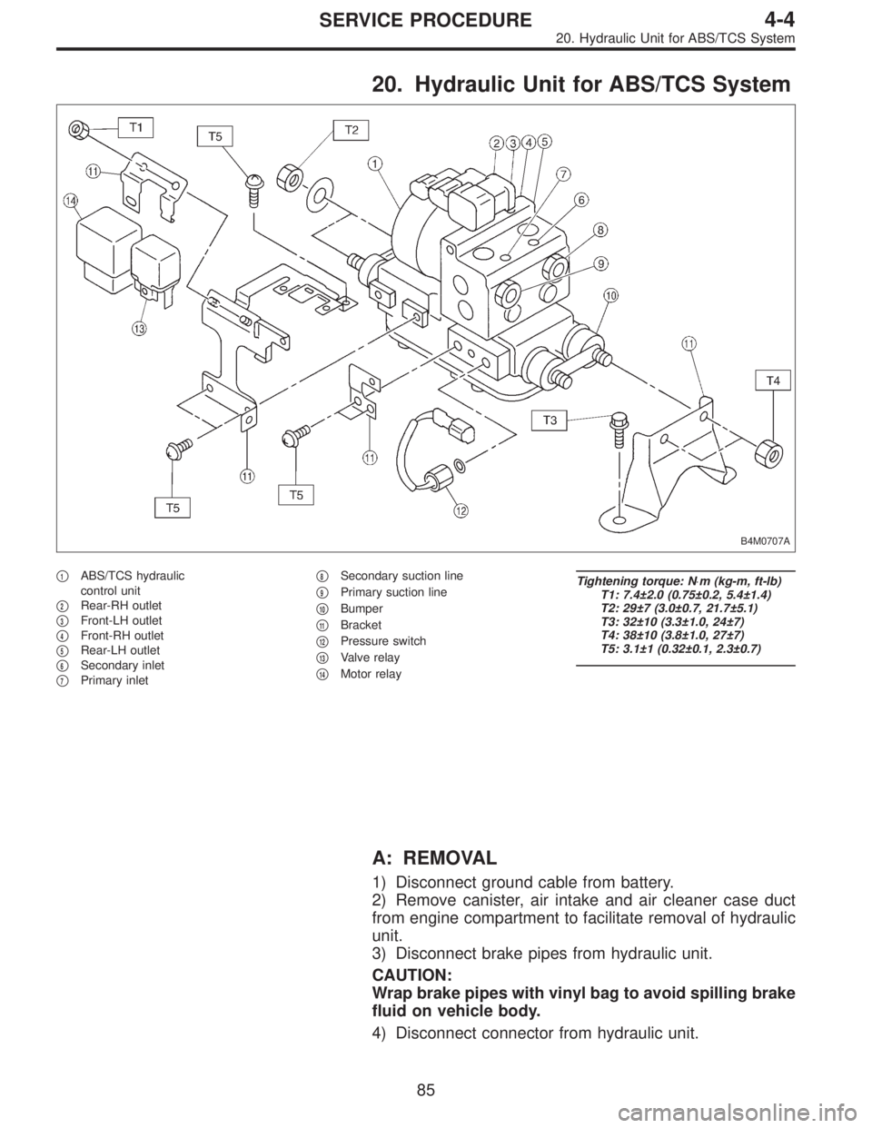
20. Hydraulic Unit for ABS/TCS System
B4M0707A
�1ABS/TCS hydraulic
control unit
�
2Rear-RH outlet
�
3Front-LH outlet
�
4Front-RH outlet
�
5Rear-LH outlet
�
6Secondary inlet
�
7Primary inlet�
8Secondary suction line
�
9Primary suction line
�
10Bumper
�
11Bracket
�
12Pressure switch
�
13Valve relay
�
14Motor relay
Tightening torque: N⋅m (kg-m, ft-lb)
T1: 7.4±2.0 (0.75±0.2, 5.4±1.4)
T2: 29±7 (3.0±0.7, 21.7±5.1)
T3: 32±10 (3.3±1.0, 24±7)
T4: 38±10 (3.8±1.0, 27±7)
T5: 3.1±1 (0.32±0.1, 2.3±0.7)
A: REMOVAL
1) Disconnect ground cable from battery.
2) Remove canister, air intake and air cleaner case duct
from engine compartment to facilitate removal of hydraulic
unit.
3) Disconnect brake pipes from hydraulic unit.
CAUTION:
Wrap brake pipes with vinyl bag to avoid spilling brake
fluid on vehicle body.
4) Disconnect connector from hydraulic unit.
85
4-4SERVICE PROCEDURE
20. Hydraulic Unit for ABS/TCS System
Page 830 of 2248
B: REMOVAL
1. ACCELERATOR PEDAL (LHD MODEL)
1) Disconnect ground cable from battery.
2) Disconnect accelerator cable from throttle body.
CAUTION:
Be careful not to kink accelerator cable.
3) Remove instrument panel lower cover from instrument
panel, and connector.
G4M0322
4) Disconnect accelerator cable from accelerator pedal
lever.
G4M0335
5) Working inside engine compartment, remove casing
cap out of the toe board by turning it clockwise.
6) Pull out the cable from the toe board hole.
G4M0321
7) Remove accelerator pedal connecting bolt from accel-
erator pedal bracket.
8
4-5SERVICE PROCEDURE
1. Pedal
Page 840 of 2248
 Disconnect accelerator cable from connector inside
engine compartment first.
G2M0280
2) Remove lock nut from accelerator cable bracket.
3) Separate accelerator cable�
1from bracket, then")
A: REMOVAL
1) Disconnect accelerator cable from connector inside
engine compartment first.
G2M0280
2) Remove lock nut from accelerator cable bracket.
3) Separate accelerator cable�
1from bracket, then unlock
inner cable.
4) Remove cable end from throttle cam using your finger-
tips.
CAUTION:
Be careful not to bend inner cable.
5) Disconnect cable end from accelerator cable bracket
inside driver compartment.
6) Remove clip inside engine compartment.
G4M0335
7) Working inside engine compartment, remove the casing
cap out of the toe board by turning it clockwise.
8) Pull out the cable from the toe board hole.
B: INSTALLATION
1) Installation is in the reverse order of removal proce-
dures.
CAUTION:
�Be careful not to kink accelerator cable.
�Make sure that holder and casing cap are securely
connected.
B4M0159A
�1Casing cap
�
2Accelerator cable
�
3Toe board
�
4Accelerator pedal bracket
�
5Holder
2) Adjustment after cable installation.
18
4-5SERVICE PROCEDURE
3. Accelerator Cable
Page 851 of 2248
1. Supplemental Restraint System
“Airbag”
Airbag system wiring harness is routed near the instrument
panel, heater unit, blower motor and control unit.
CAUTION:
�All Airbag system wiring harness and connectors
are colored yellow. Do not use electrical test equip-
ment on these circuit.
�Be careful not to damage Airbag system wiring har-
ness when servicing the instrument panel, heater unit,
blower motor and control unit.
2. Heater Unit
A: REMOVAL AND INSTALLATION
1) Disconnect GND cable from battery.
2) Remove heater hoses (inlet, outlet) in engine compart-
ment.
NOTE:
Drain as much coolant from heater unit as possible, and
plug disconnected hose with cloth.
3) Remove instrument panel.
4) Remove steering support beam.
5) Remove evaporator. (With A/C model)
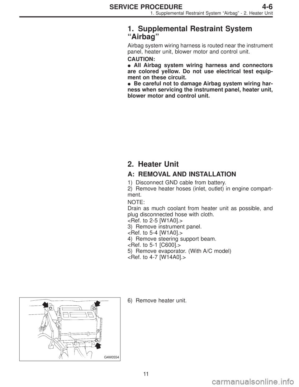
G4M0554
6) Remove heater unit.
11
4-6SERVICE PROCEDURE
1. Supplemental Restraint System“Airbag”- 2. Heater Unit
Page 852 of 2248
1. Supplemental Restraint System
“Airbag”
Airbag system wiring harness is routed near the instrument
panel, heater unit, blower motor and control unit.
CAUTION:
�All Airbag system wiring harness and connectors
are colored yellow. Do not use electrical test equip-
ment on these circuit.
�Be careful not to damage Airbag system wiring har-
ness when servicing the instrument panel, heater unit,
blower motor and control unit.
2. Heater Unit
A: REMOVAL AND INSTALLATION
1) Disconnect GND cable from battery.
2) Remove heater hoses (inlet, outlet) in engine compart-
ment.
NOTE:
Drain as much coolant from heater unit as possible, and
plug disconnected hose with cloth.
3) Remove instrument panel.
4) Remove steering support beam.
5) Remove evaporator. (With A/C model)
G4M0554
6) Remove heater unit.
11
4-6SERVICE PROCEDURE
1. Supplemental Restraint System“Airbag”- 2. Heater Unit
 Disconnect front ABS sensor connector located in
engine compartment.
B4M0079A
2) Remove bolts which secure sensor harness to strut.
G4M0451
3) Remove b")

1) Disconnect ground cable from battery.
2) Disconnect accelerator cable from throttle body.
CAUTION:
Be careful not to kink accelerator cable.
3) Remove in")