Page 948 of 2248
1. Hood
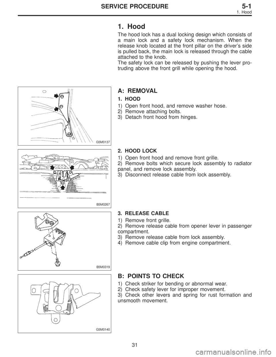
The hood lock has a dual locking design which consists of
a main lock and a safety lock mechanism. When the
release knob located at the front pillar on the driver’s side
is pulled back, the main lock is released through the cable
attached to the knob.
The safety lock can be released by pushing the lever pro-
truding above the front grill while opening the hood.
G5M0137
A: REMOVAL
1. HOOD
1) Open front hood, and remove washer hose.
2) Remove attaching bolts.
3) Detach front hood from hinges.
B5M0267
2. HOOD LOCK
1) Open front hood and remove front grille.
2) Remove bolts which secure lock assembly to radiator
panel, and remove lock assembly.
3) Disconnect release cable from lock assembly.
B5M0319
3. RELEASE CABLE
1) Remove front grille.
2) Remove release cable from opener lever in passenger
compartment.
3) Remove release cable from lock assembly.
4) Remove cable clip from engine compartment.
G5M0140
B: POINTS TO CHECK
1) Check striker for bending or abnormal wear.
2) Check safety lever for improper movement.
3) Check other levers and spring for rust formation and
unsmooth movement.
31
5-1SERVICE PROCEDURE
1. Hood
Page 954 of 2248
B5M0376
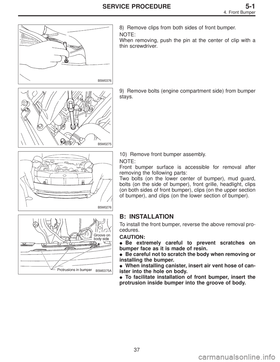
8) Remove clips from both sides of front bumper.
NOTE:
When removing, push the pin at the center of clip with a
thin screwdriver.
B5M0275
9) Remove bolts (engine compartment side) from bumper
stays.
B5M0276
10) Remove front bumper assembly.
NOTE:
Front bumper surface is accessible for removal after
removing the following parts:
Two bolts (on the lower center of bumper), mud guard,
bolts (on the side of bumper), front grille, headlight, clips
(on both sides of front bumper), clips (on the upper section
of bumper), and clips (on the lower section of bumper).
B5M0375A
B: INSTALLATION
To install the front bumper, reverse the above removal pro-
cedures.
CAUTION:
�Be extremely careful to prevent scratches on
bumper face as it is made of resin.
�Be careful not to scratch the body when removing or
installing the bumper.
�When installing canister, insert air vent hose of can-
ister into the hole on body.
�To facilitate installation of front bumper, insert the
protrusion inside bumper into the groove of body.
37
5-1SERVICE PROCEDURE
4. Front Bumper
Page 1088 of 2248
3. Spark Plug
A: REMOVAL AND INSTALLATION
CAUTION:
All spark plugs installed on an engine, must be of the
same heat range.
Spark plug:
CHAMPION: RC10YC4
(Alternate)
NGK: BKR6E-11
NIPPONDENSO: K20PR-U11
1) Remove spark plug cords by pulling boot, not cord itself.
2) Remove spark plugs.
3) When installing spark plugs on cylinder head, use spark
plug wrench.
Tightening torque (Spark plug):
20.6±2.9 N⋅m (2.10±0.30 kg-m, 15.19±2.14 ft-lb)
CAUTION:
The above torque should be only applied to new spark
plugs without oil on their threads.
In case their threads are lubricated, the torque should
be reduced by approximately 1/3 of the specified
torque in order to avoid their over-stressing.
4) Connect spark plug cords.
G6M0086
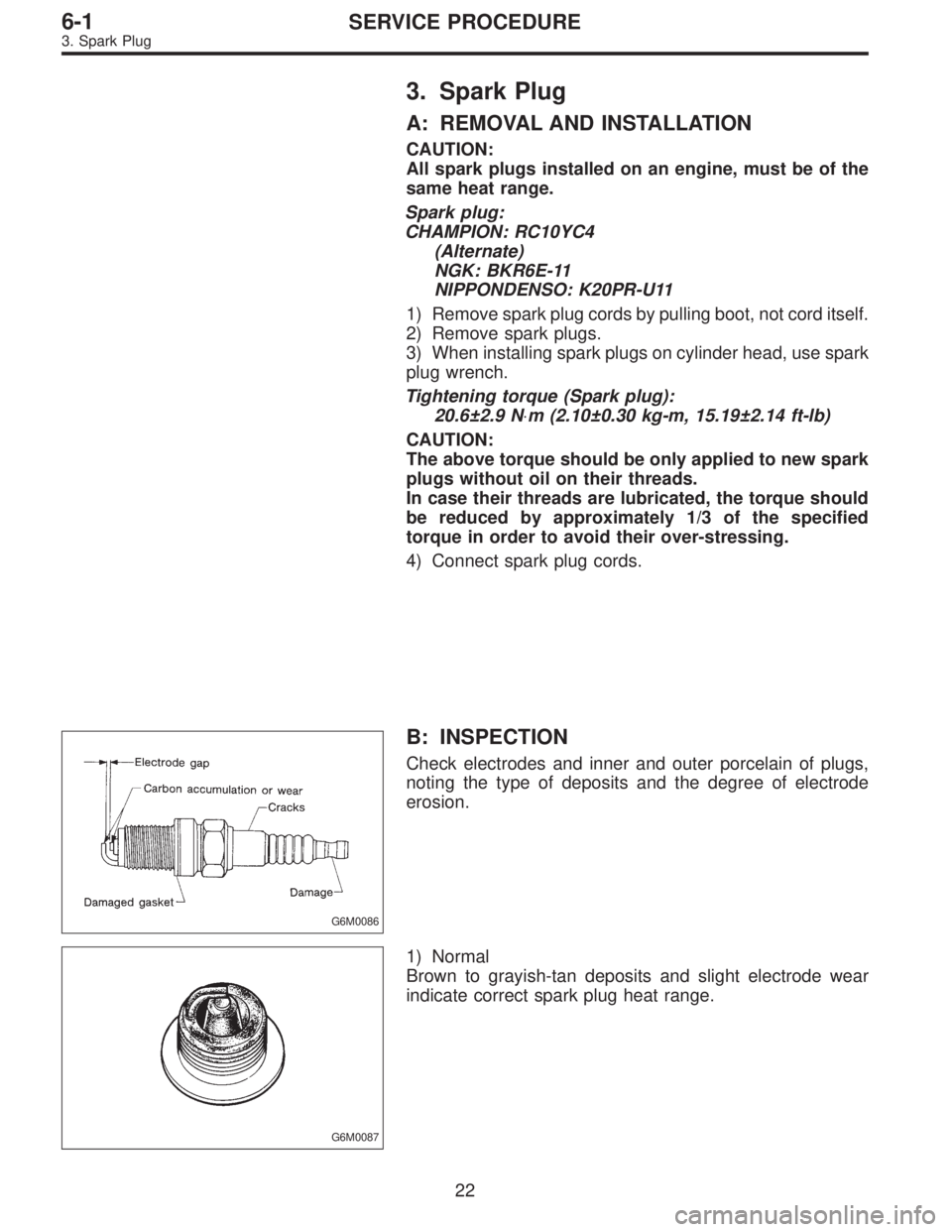
B: INSPECTION
Check electrodes and inner and outer porcelain of plugs,
noting the type of deposits and the degree of electrode
erosion.
G6M0087
1) Normal
Brown to grayish-tan deposits and slight electrode wear
indicate correct spark plug heat range.
22
6-1SERVICE PROCEDURE
3. Spark Plug
Page 1089 of 2248
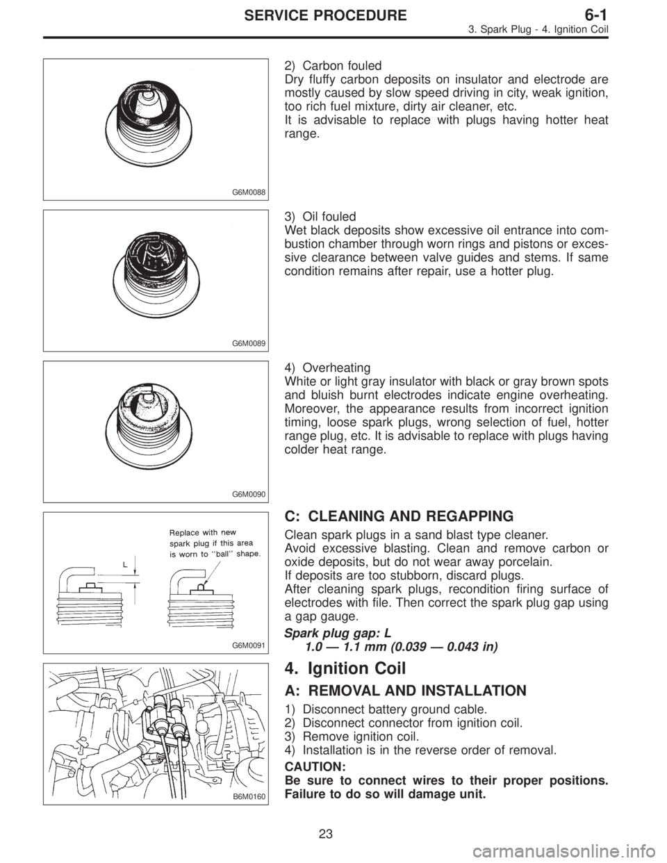
G6M0088
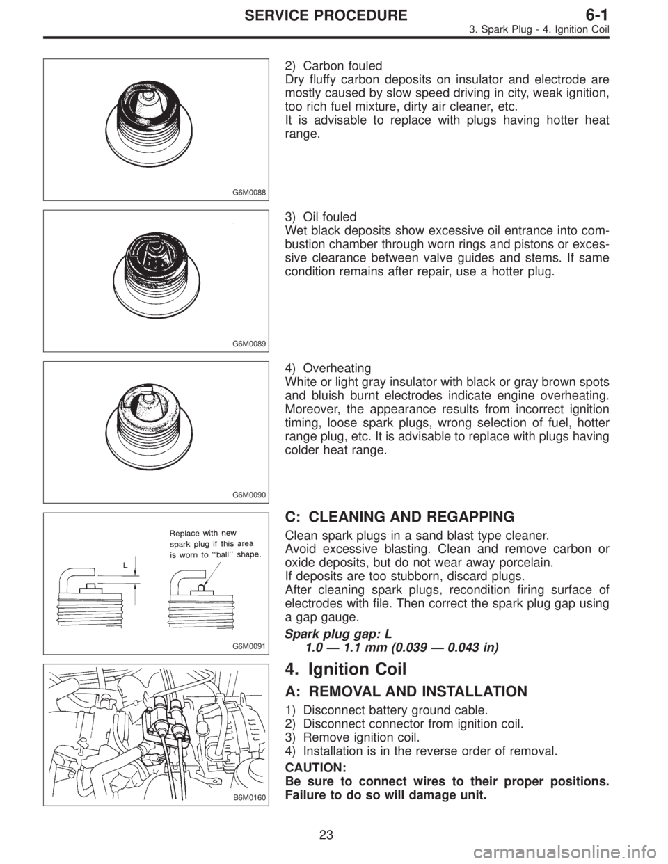
2) Carbon fouled
Dry fluffy carbon deposits on insulator and electrode are
mostly caused by slow speed driving in city, weak ignition,
too rich fuel mixture, dirty air cleaner, etc.
It is advisable to replace with plugs having hotter heat
range.
G6M0089
3) Oil fouled
Wet black deposits show excessive oil entrance into com-
bustion chamber through worn rings and pistons or exces-
sive clearance between valve guides and stems. If same
condition remains after repair, use a hotter plug.
G6M0090
4) Overheating
White or light gray insulator with black or gray brown spots
and bluish burnt electrodes indicate engine overheating.
Moreover, the appearance results from incorrect ignition
timing, loose spark plugs, wrong selection of fuel, hotter
range plug, etc. It is advisable to replace with plugs having
colder heat range.
G6M0091
C: CLEANING AND REGAPPING
Clean spark plugs in a sand blast type cleaner.
Avoid excessive blasting. Clean and remove carbon or
oxide deposits, but do not wear away porcelain.
If deposits are too stubborn, discard plugs.
After cleaning spark plugs, recondition firing surface of
electrodes with file. Then correct the spark plug gap using
a gap gauge.
Spark plug gap: L
1.0—1.1 mm (0.039—0.043 in)
B6M0160
4. Ignition Coil
A: REMOVAL AND INSTALLATION
1) Disconnect battery ground cable.
2) Disconnect connector from ignition coil.
3) Remove ignition coil.
4) Installation is in the reverse order of removal.
CAUTION:
Be sure to connect wires to their proper positions.
Failure to do so will damage unit.
23
6-1SERVICE PROCEDURE
3. Spark Plug - 4. Ignition Coil
Page 1090 of 2248
G6M0088
2) Carbon fouled
Dry fluffy carbon deposits on insulator and electrode are
mostly caused by slow speed driving in city, weak ignition,
too rich fuel mixture, dirty air cleaner, etc.
It is advisable to replace with plugs having hotter heat
range.
G6M0089
3) Oil fouled
Wet black deposits show excessive oil entrance into com-
bustion chamber through worn rings and pistons or exces-
sive clearance between valve guides and stems. If same
condition remains after repair, use a hotter plug.
G6M0090
4) Overheating
White or light gray insulator with black or gray brown spots
and bluish burnt electrodes indicate engine overheating.
Moreover, the appearance results from incorrect ignition
timing, loose spark plugs, wrong selection of fuel, hotter
range plug, etc. It is advisable to replace with plugs having
colder heat range.
G6M0091
C: CLEANING AND REGAPPING
Clean spark plugs in a sand blast type cleaner.
Avoid excessive blasting. Clean and remove carbon or
oxide deposits, but do not wear away porcelain.
If deposits are too stubborn, discard plugs.
After cleaning spark plugs, recondition firing surface of
electrodes with file. Then correct the spark plug gap using
a gap gauge.
Spark plug gap: L
1.0—1.1 mm (0.039—0.043 in)
B6M0160
4. Ignition Coil
A: REMOVAL AND INSTALLATION
1) Disconnect battery ground cable.
2) Disconnect connector from ignition coil.
3) Remove ignition coil.
4) Installation is in the reverse order of removal.
CAUTION:
Be sure to connect wires to their proper positions.
Failure to do so will damage unit.
23
6-1SERVICE PROCEDURE
3. Spark Plug - 4. Ignition Coil
Page 1106 of 2248
B6M0336A
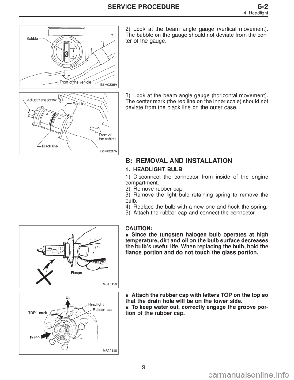
2) Look at the beam angle gauge (vertical movement).
The bubble on the gauge should not deviate from the cen-
ter of the gauge.
B6M0337A
3) Look at the beam angle gauge (horizontal movement).
The center mark (the red line on the inner scale) should not
deviate from the black line on the outer case.
B: REMOVAL AND INSTALLATION
1. HEADLIGHT BULB
1) Disconnect the connector from inside of the engine
compartment.
2) Remove rubber cap.
3) Remove the light bulb retaining spring to remove the
bulb.
4) Replace the bulb with a new one and hook the spring.
5) Attach the rubber cap and connect the connector.
M6A0139
CAUTION:
�Since the tungsten halogen bulb operates at high
temperature, dirt and oil on the bulb surface decreases
the bulb’s useful life. When replacing the bulb, hold the
flange portion and do not touch the glass portion.
M6A0140
�Attach the rubber cap with letters TOP on the top so
that the drain hole will be on the lower side.
�To keep water out, correctly engage the groove por-
tion of the rubber cap.
9
6-2SERVICE PROCEDURE
4. Headlight
Page 1115 of 2248
6. Turn Signal and Hazard Warning
Light
A: REMOVAL AND INSTALLATION
1. FRONT TURN SIGNAL LIGHT
Refer to 6-2 [W4B2] as for removal and installation of front
turn signal light.
NOTE:
The front turn signal light is united with headlight assem-
bly.
2. REAR COMBINATION LIGHT
Refer to 6-2 [W5A1] as for removal and installation of rear
combination light.
3. COMBINATION SWITCH
Refer to 6-2 [W4B3] as for removal and installation of com-
bination switch.
B6M0063
4. HAZARD SWITCH
1) Remove center panel from instrument panel.
5-4 [W1A0].>
2) Disconnect connector of hazard switch from body har-
ness.
3) Remove hazard switch from center panel.
B6M0343A
5. TURN SIGNAL AND HAZARD UNIT
1) Remove instrument panel lower cover.
2) Remove engine hood opener lever bracket.
3) Disconnect connector of turn signal and hazard unit.
4) Remove screw, and then remove turn signal and haz-
ard unit from bracket.
18
6-2SERVICE PROCEDURE
6. Turn Signal and Hazard Warning Light
Page 1121 of 2248
B6M0107A
B: REMOVAL AND INSTALLATION
1. BLADE
Pull out blade following the arrow direction from arm while
pushing up locking clip.
G6M0118
2. WIPER ARM
1) Open engine hood.
2) Remove cap of wiper arm installation nut.
3) Remove the nut which secures wiper arm.
4) Remove wiper arm.
5) Installation is in the reverse order of removal.
NOTE:
Remove metal sludge from the wiper arm fixture before
installing it.
Tightening torque:
20±3 N⋅m (2.0±0.3 kg-m, 14.5±2.2 ft-lb)
3. WIPER MOTOR AND LINK
1) Detach weatherstrip and cowl panel.
[W10A0].>
NOTE:
Apply silicone oil or soap water to both sides of cowl net to
facilitate removal.
B6M0108
2) Disconnect connector of wiper motor.
3) Remove motor attaching bolts.
Tightening torque:
5.9±1.5 N⋅m (0.6±0.15 kg-m, 4.3±1.1 ft-lb)
23
6-2SERVICE PROCEDURE
10. Front Wiper and Washer