Page 16 of 2248
5) Check idle speed when unloaded. (With headlights,
heater fan, rear defroster, radiator fan, air conditioning, etc.
OFF)
Idle speed (No load and gears in neutral (MT) or N or
P (AT) position):
700±100 rpm
6) Check idle speed when loaded. (Turn air conditioning
switch to“ON”and operate compressor for at least one
minute before measurement.)
Idle speed [A/C“ON”, no load and gears in neutral
(MT) or N or P (AT) position]:
850±50 rpm
CAUTION:
Never rotate idle adjusting screw. If idle speed is out
of specifications, refer to General On-board Diagnosis
Table under “2-7 On-Board Diagnostics II System”.
4
2-2
3. Engine Idle Speed
Page 372 of 2248

G3M0291
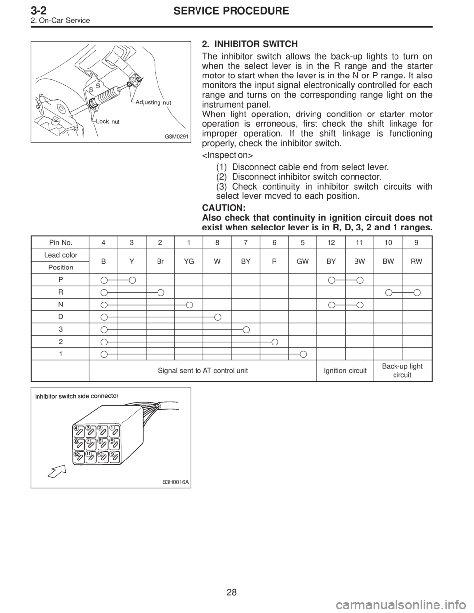
2. INHIBITOR SWITCH
The inhibitor switch allows the back-up lights to turn on
when the select lever is in the R range and the starter
motor to start when the lever is in the N or P range. It also
monitors the input signal electronically controlled for each
range and turns on the corresponding range light on the
instrument panel.
When light operation, driving condition or starter motor
operation is erroneous, first check the shift linkage for
improper operation. If the shift linkage is functioning
properly, check the inhibitor switch.
(1) Disconnect cable end from select lever.
(2) Disconnect inhibitor switch connector.
(3) Check continuity in inhibitor switch circuits with
select lever moved to each position.
CAUTION:
Also check that continuity in ignition circuit does not
exist when selector lever is in R, D, 3, 2 and 1 ranges.
PinNo. 432187651211109
Lead color
B Y Br YG W BY R GW BY BW BW RW
Position
P��
��
R����
N����
D��
3��
2��
1��
Signal sent to AT control unit Ignition circuitBack-up light
circuit
B3H0016A
28
3-2SERVICE PROCEDURE
2. On-Car Service
Page 801 of 2248

3. CONDITIONS FOR COMPLETION OF AIR
BLEEDING CONTROL
When any of the following conditions occurs, ABS and TCS
warning lights illuminate. Air bleeding control stops, while
the ABS and TCS function will then stop. The brake sys-
tem functions as a conventional brake system.
1) When the speed of at least one wheel reaches 10 km/h
(6 MPH).
2) When terminal No. 4 is separated from diagnosis termi-
nal. (When select monitor is not used.)
3) When pump motor remains ON for two minutes.
4) When TCS valve remains open for two minutes.
5) When outlet valve remains closed for two minutes.
6) When malfunction is detected.
NOTE:
When a malfunction is detected the air bleeding operation
stops and the trouble codes are stored in memory.
B4M0082C
C: AIR BLEEDING CONTROL WITH
DIAGNOSIS CONNECTOR
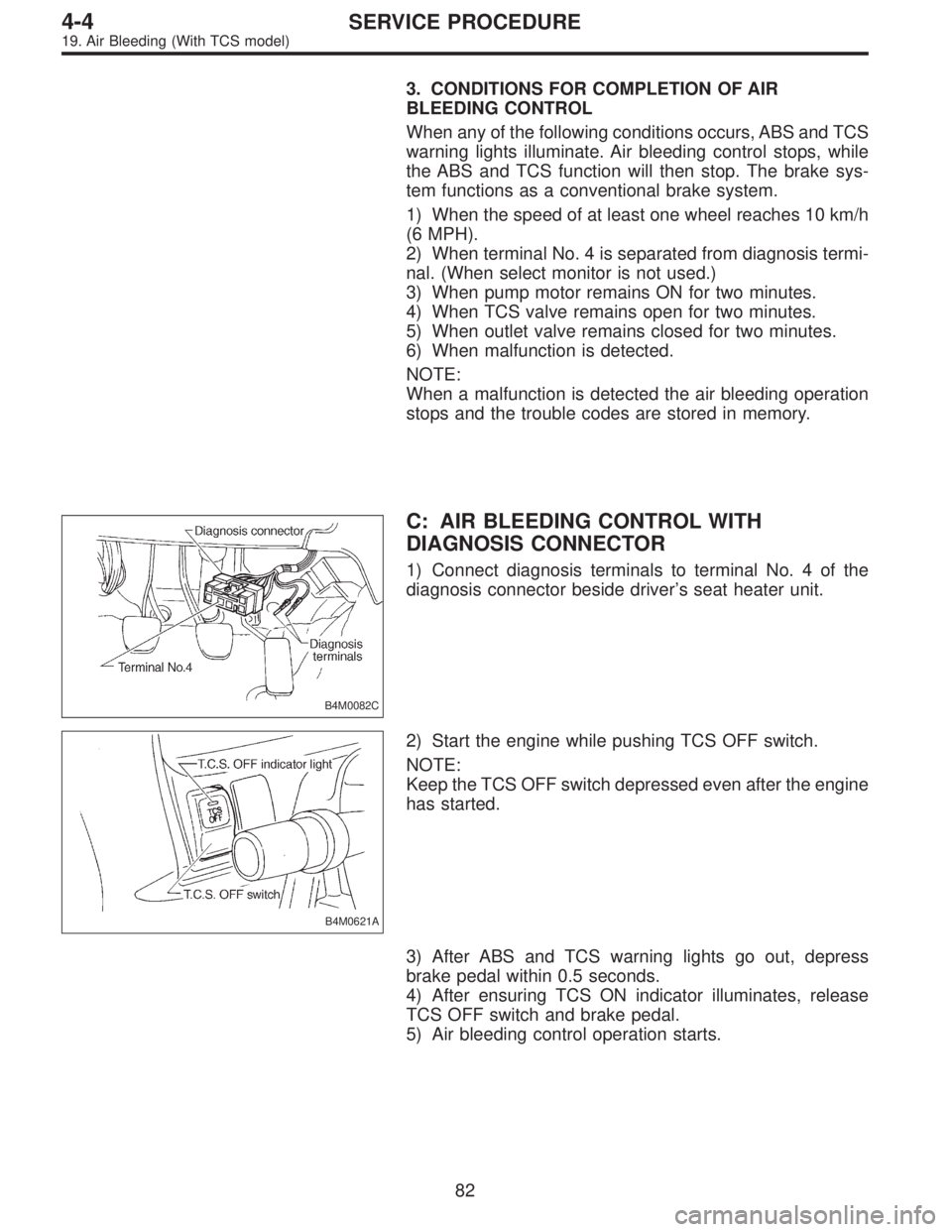
1) Connect diagnosis terminals to terminal No. 4 of the
diagnosis connector beside driver’s seat heater unit.
B4M0621A
2) Start the engine while pushing TCS OFF switch.
NOTE:
Keep the TCS OFF switch depressed even after the engine
has started.
3) After ABS and TCS warning lights go out, depress
brake pedal within 0.5 seconds.
4) After ensuring TCS ON indicator illuminates, release
TCS OFF switch and brake pedal.
5) Air bleeding control operation starts.
82
4-4SERVICE PROCEDURE
19. Air Bleeding (With TCS model)
Page 808 of 2248

D: ABS SEQUENCE CONTROL
1) Under the ABS sequence control, after the hydraulic
unit solenoid valve is driven, the operation of the hydraulic
unit can be checked by means of the brake tester or pres-
sure gauge.
2) ABS sequence control can be started by diagnosis con-
nector or select monitor.
B4M0082C
1. OPERATIONAL GUIDELINES OF THE ABS
SEQUENCE CONTROL WITH DIAGNOSIS
CONNECTOR
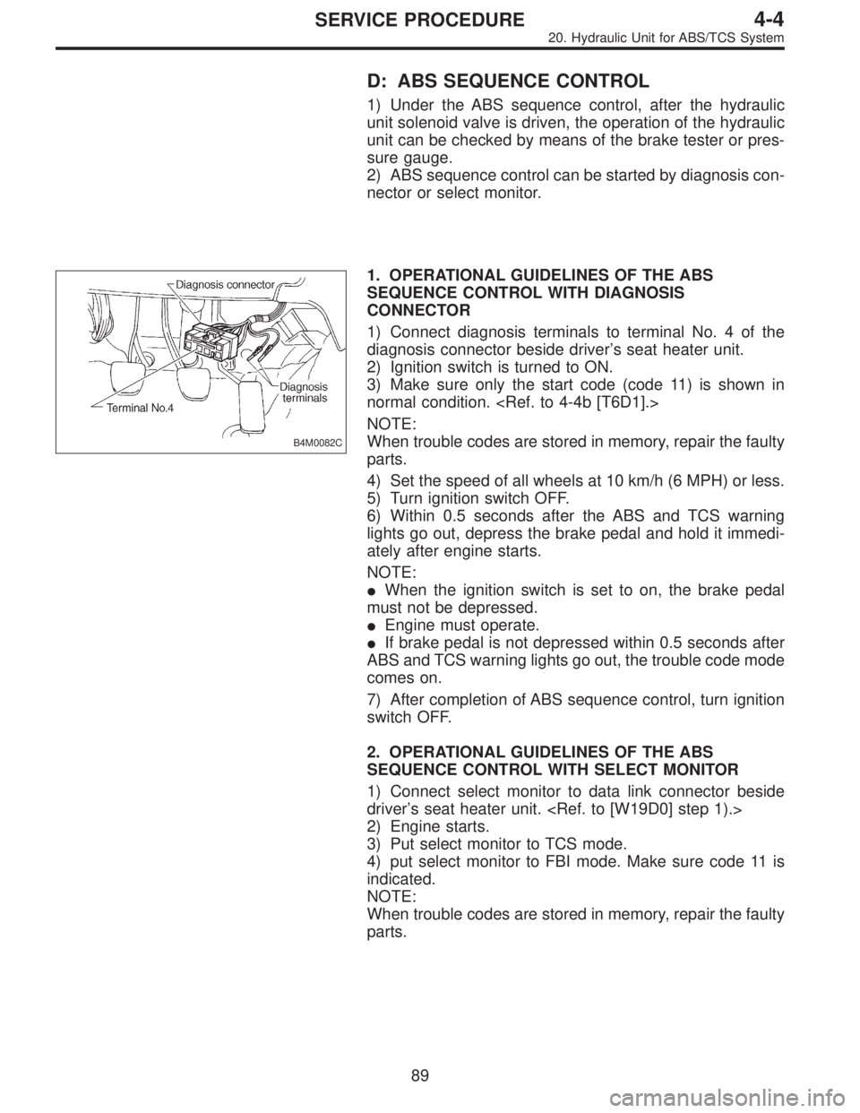
1) Connect diagnosis terminals to terminal No. 4 of the
diagnosis connector beside driver’s seat heater unit.
2) Ignition switch is turned to ON.
3) Make sure only the start code (code 11) is shown in
normal condition.
NOTE:
When trouble codes are stored in memory, repair the faulty
parts.
4) Set the speed of all wheels at 10 km/h (6 MPH) or less.
5) Turn ignition switch OFF.
6) Within 0.5 seconds after the ABS and TCS warning
lights go out, depress the brake pedal and hold it immedi-
ately after engine starts.
NOTE:
�When the ignition switch is set to on, the brake pedal
must not be depressed.
�Engine must operate.
�If brake pedal is not depressed within 0.5 seconds after
ABS and TCS warning lights go out, the trouble code mode
comes on.
7) After completion of ABS sequence control, turn ignition
switch OFF.
2. OPERATIONAL GUIDELINES OF THE ABS
SEQUENCE CONTROL WITH SELECT MONITOR
1) Connect select monitor to data link connector beside
driver’s seat heater unit.
2) Engine starts.
3) Put select monitor to TCS mode.
4) put select monitor to FBI mode. Make sure code 11 is
indicated.
NOTE:
When trouble codes are stored in memory, repair the faulty
parts.
89
4-4SERVICE PROCEDURE
20. Hydraulic Unit for ABS/TCS System
Page 810 of 2248
3. CONDITIONS FOR COMPLETION OF ABS
SEQUENCE CONTROL
When the following conditions develop, the ABS sequence
control stops and ABS and TCS warning lights come on
while the ABS and TCS function will then stop. The brake
system functions as a conventional brake system.
1) When the speed of at least one wheel reaches 10 km/h
(6 MPH).
2) When terminal No.4 is separated from ground. (When
select monitor is not used.)
3) When the brake pedal is released during sequence con-
trol and the braking lamp switch is set to off.
4) After completion of the sequence control.
5) When malfunction is detected.
NOTE:
When malfunction has been detected and the ABS
sequence control operation has stopped, the trouble codes
are stored in memory.
91
4-4SERVICE PROCEDURE
20. Hydraulic Unit for ABS/TCS System
Page 814 of 2248

F: TCS SEQUENCE CONTROL
1) Under the TCS sequence control, after the hydraulic
unit solenoid valve is driven, the operation of the hydraulic
unit can be checked by means of the brake tester or pres-
sure gauge.
2) TCS sequence control can be started by diagnosis con-
nector or select monitor.
B4M0082C
1. OPERATIONAL GUIDELINES OF THE TCS
SEQUENCE CONTROL WITH DIAGNOSIS
CONNECTOR
1) Connect diagnosis terminals to terminal No. 4 of the
diagnosis connector beside driver seat heater unit.
2) Ignition switch is turned to ON.
3) Make sure only the start code (code 11) is shown in
normal condition.
NOTE:
When trouble codes are stored in memory, repair the faulty
parts.
4) Set the speed of all wheels at 10 km/h (6 MPH) or less.
5) Turn ignition switch OFF.
6) Start engine, and within 0.5 seconds after the ABS
warning light and TCS warning light go out, press TCS OFF
switch. Within 1.0 second thereafter, release and press the
switch again. Then, keep the switch pressed.
NOTE:
�When the TCS sequence control is set to on, the brake
pedal must not be depressed.
�Engine must operate.
�When TCS OFF switch is not depressed within 0.5 sec-
onds after ABS and TCS warning lights turn off, the trouble
code mode comes on.
7) After completion of TCS sequence control, turn ignition
switch OFF.
95
4-4SERVICE PROCEDURE
20. Hydraulic Unit for ABS/TCS System
Page 816 of 2248
3. CONDITIONS FOR COMPLETION OF TCS
SEQUENCE CONTROL
When the following conditions develop, the TCS sequence
control stops and ABS and TCS warning lights come on
while the ABS and TCS function will then stop. The brake
system functions as a conventional brake system.
1) When the speed of at least one wheel reaches 10 km/h
(6 MPH).
2) When terminal No. 4 is separated from ground. (When
select monitor is not used.)
3) When the brake pedal is depressed during sequence
control and the braking lamp switch is set to ON.
4) When TCS OFF switch is released. (When select moni-
tor is not used.)
5) After completion of the TCS sequence control.
6) When output signal to break TCS control is emitted from
ECM.
7) When malfunction is detected.
NOTE:
When malfunction has been detected and the TCS
sequence control operation has stopped, the trouble codes
are stored in memory.
97
4-4SERVICE PROCEDURE
20. Hydraulic Unit for ABS/TCS System
Page 939 of 2248
4. Datum Points and Dimensions
Concerning On-Board Aiming
Adjustment
If headlight aiming is misaligned due to damaged body
panel, repair headlight mating surface using body and
headlight datum points as a guide.
NOTE:
It is recommended to conduct On-Board Aiming Adjust-
ment with headlights turned off.
If turned on during the adjustment, the duration should be
within two minutes.
B5M0364
Unit: mm (in)
22
5-1SERVICE DATA
4. Datum Points and Dimensions Concerning On-Board Aiming Adjustment