Page 137 of 2248

1. Engine Cooling System
Trouble Possible cause Corrective action
Over-heatinga. Insufficient engine coolantReplenish engine coolant, inspect for leakage, and
repair.
b. Loose timing belt Repair or replace timing belt tensioner.
c. Oil on drive belt Replace.
d. Malfunction of thermostat Replace.
e. Malfunction of engine coolant pump Replace.
f. Clogged engine coolant passage Clean.
g. Improper ignition timingInspect and repair ignition control system.
h. Clogged or leaking radiator Clean or repair, or replace.
i. Improper engine oil in engine coolant Replace engine coolant.
j. Air/fuel mixture ratio too leanInspect and repair fuel injection system.
k. Excessive back pressure in exhaust system Clean or replace.
l. Insufficient clearance between piston and cylinder Adjust or replace.
m. Slipping clutch Repair or replace.
n. Dragging brake Adjust.
o. Improper transmission oil Replace.
p. Defective thermostat Replace.
q. Malfunction of electric fanInspect radiator fan relay, engine coolant temperature
sensor or radiator motor and replace there.
Over-coolinga. Atmospheric temperature extremely low Partly cover radiator front area.
b. Defective thermostat Replace.
Engine coolant
leaks.a. Loosened or damaged connecting units on hoses Repair or replace.
b. Leakage from engine coolant pump Replace.
c. Leakage from engine coolant pipe Repair or replace.
d. Leakage around cylinder head gasket Retighten cylinder head bolts or replace gasket.
e. Damaged or cracked cylinder head and crankcase Repair or replace.
f. Damaged or cracked thermostat case Repair or replace.
g. Leakage from radiator Repair or replace.
Noisea. Defective drive belt Replace.
b. Defective radiator fan Replace.
c. Defective engine coolant pump bearing Replace engine coolant pump.
d. Defective engine coolant pump mechanical seal Replace engine coolant pump.
19
2-5DIAGNOSTICS
1. Engine Cooling System
Page 161 of 2248
B2M0342
12) Disconnect brake booster hose.
B2M0343
13) Remove EGR pipe.
G2M0370
14) Disconnect canister hose from pipe.
B2M0019
15) Disconnect engine harness connectors from bulkhead
harness connectors.
B2M0345A
16) Disconnect connectors from engine coolant tempera-
ture sensor�
1and thermometer�2.
10
2-7SERVICE PROCEDURE
4. Intake Manifold
Page 256 of 2248
11) Install front exhaust pipe and center exhaust pipe.
12) Connect hoses, connectors and cables.
(1) Connect the following hoses.
�Fuel delivery hose, return hose and evaporation
hose
�Heater inlet and outlet hoses
�Brake booster vacuum hose
(2) Connect the following connectors.
�Engine ground terminal
�Engine harness connectors
�Front oxygen sensor connector
�Rear oxygen sensor connector
�Alternator connector and terminal
�A/C compressor connectors (With A/C)
(3) Connect the following cables.
�Accelerator cable
�Cruise control cables (With cruise control)
�Clutch cable
�Clutch release spring
CAUTION:
After connecting each cable, adjust them.
G2M0271
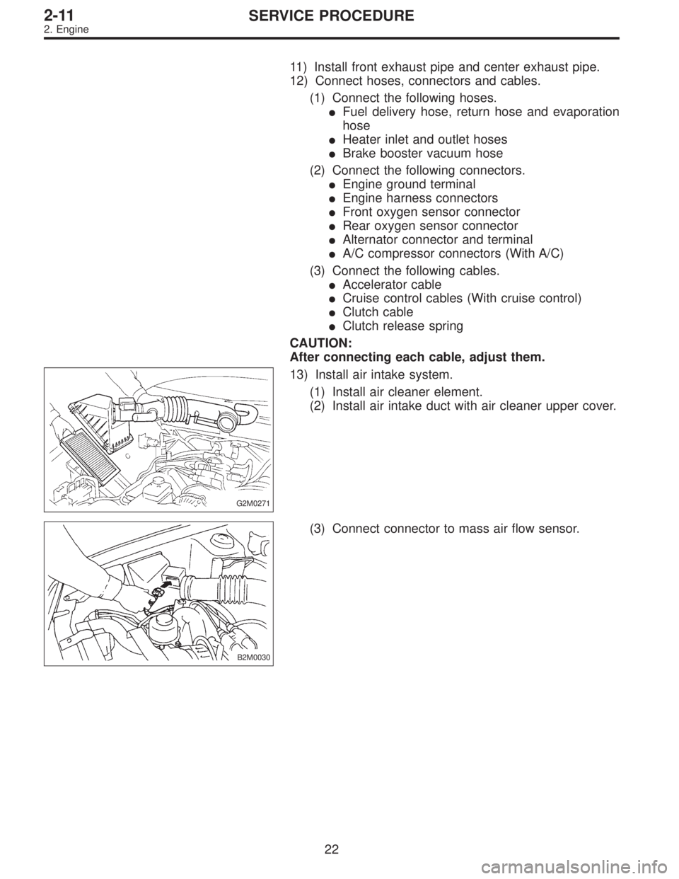
13) Install air intake system.
(1) Install air cleaner element.
(2) Install air intake duct with air cleaner upper cover.
B2M0030
(3) Connect connector to mass air flow sensor.
22
2-11SERVICE PROCEDURE
2. Engine
Page 492 of 2248
2. SIDE OIL SEAL
1) Disconnect ground cable from battery.
2) Move selector lever or gear shift lever to“N”.
3) Release the parking brake.
4) Loosen both wheel nuts.
5) Jack-up the vehicle and support it with rigid racks.
6) Remove wheels.
7) Remove rear exhaust pipe and muffler.
G3M0038
8) Remove the DOJ of rear drive shaft from rear differen-
tial.
(1) Remove the A.B.S. sensor cable clamp and park-
ing brake cable clamp from bracket.
G3M0039
(2) Remove the A.B.S. sensor cable clamp from the
trailing link.
G3M0040
(3) Remove the A.B.S. sensor cable clamp and park-
ing brake cable guide from the trailing link.
G3M0041
(4) Remove the rear stabilizer link.
16
3-4SERVICE PROCEDURE
2. Rear Differential
Page 538 of 2248
G4M0504
4) Remove brake hose clamp and disconnect brake hose
from strut. Attach brake hose to body using gum tape.
5) Scribe an alignment mark on the camber adjusting bolt
which secures strut to housing.
6) Remove bolt securing the A.B.S. sensor harness.
(A.B.S. equipped models.)
G4M0505
7) Remove two bolts securing housing to strut.
CAUTION:
While holding head of adjusting bolt, loosen self-lock-
ing nut.
8) Remove the three nuts securing strut mount to body.
G4M0506
B: DISASSEMBLY
1) Using a coil spring compressor, compress coil spring.
G4M0507
2) Using ST, remove self-locking nut.
ST 927760000 STRUT MOUNT SOCKET
3) Remove strut mount, upper spring seat and rubber seat
from strut.
4) Gradually decreasing compression force of spring
compressor, and remove coil spring.
5) Remove dust cover and helper.
21
4-1SERVICE PROCEDURE
4. Front Strut
Page 541 of 2248
 Pull the piston rod fully upward, and install rubber seat
and spring seat.
NOTE:
Ensure that upper spring seat is positioned with“OUT”
mark facing outward.
8) Install strut mount to the")
G4M0511
7) Pull the piston rod fully upward, and install rubber seat
and spring seat.
NOTE:
Ensure that upper spring seat is positioned with“OUT”
mark facing outward.
8) Install strut mount to the piston rod, and tighten the
self-locking nut temporarily.
CAUTION:
Be sure to use a new self-locking nut.
G4M0507
9) Using hexagon wrench to prevent strut rod from turning,
tighten self-locking nut with ST.
Tightening torque:
54±5 N⋅m (5.5±0.5 kg-m, 39.8±3.6 ft-lb)
ST 927760000 STRUT MOUNT SOCKET
10) Loosen the coil spring carefully.
E: INSTALLATION
1) Install strut mount at upper side of strut to body and
tighten with nuts.
Tightening torque:
20±6 N⋅m (2.0±0.6 kg-m, 14.5±4.3 ft-lb)
2) Connect housing to lower side of strut.
3) Position aligning mark on camber adjusting bolt with
aligning mark on lower side bracket of strut.
CAUTION:
�While holding head of adjusting bolt, tighten self-
locking nut.
�Be sure to use new self-locking nut.
Tightening torque:
152±20 N⋅m (15.5±2.0 kg-m, 112±14 ft-lb)
4) Install A.B.S. sensor harness to strut. (A.B.S. equipped
models.)
Tightening torque:
152±20 N⋅m (15.5±2.0 kg-m, 112±14 ft-lb)
5) Install brake hose at lower side of strut with clamp.
G4M0503
6) Install union bolts which secure brake caliper to brake
hose.
Tightening torque:
18±3 N⋅m (1.8±0.3 kg-m, 13.0±2.2 ft-lb)
CAUTION:
Be sure to bleed air from brake system.
7) Install wheels.
NOTE:
Check wheel alignment and adjust if necessary.
24
4-1SERVICE PROCEDURE
4. Front Strut
Page 558 of 2248
 Install strut mount cap.
2) Tighten self-locking nut used to secure strut mount to
vehicle body.
CAUTION:
Use a new self-locking nut.
NOTE:
Tighten strut mount and cap as a unit.
Ti")
E: INSTALLATION
1) Install strut mount cap.
2) Tighten self-locking nut used to secure strut mount to
vehicle body.
CAUTION:
Use a new self-locking nut.
NOTE:
Tighten strut mount and cap as a unit.
Tightening torque:
20±6 N⋅m (2.0±0.6 kg-m, 14.5±4.3 ft-lb)
3) Tighten bolts securing rear strut to housing.
Tightening torque:
196
+39
�10N⋅m (20.0+4.0
�1.0kg-m, 145+29
�7ft-lb)
CAUTION:
Use a new self-locking nut.
4) Models with rear disc brakes:
Tighten brake hose union bolt on brake caliper.
Tightening torque:
18±3 N⋅m (1.8±0.3 kg-m, 13.0±2.2 ft-lb)
Models with rear drum brakes:
Connect brake hose to brake pipe.
Tightening torque:
15
+3
�2N⋅m (1.5+0.3
�0.2kg-m, 10.8+2.2
�1.4ft-lb)
5) Insert brake hose clip between brake hose and lower
side of strut.
CAUTION:
�Check that hose clip is positioned properly.
�Check brake hose for twisting, or excessive tension.
�Models equipped with A.B.S.:
Do not subject A.B.S. sensor harness to excessive ten-
sion.
6) Be sure to bleed air from brake system.
7) Lower vehicle and tighten wheel nut.
Tightening torque:
88±10 N⋅m (9±1 kg-m, 65±7 ft-lb)
8) Sedan:
Install rear seat backrest and rear seat cushion.
Wagon:
Install strut cap of rear quarter trim.
NOTE:
Check wheel alignment and adjust if necessary.
41
4-1SERVICE PROCEDURE
9. Rear Strut
Page 576 of 2248
 Install transverse link ball joint to housing.
Tightening torque:
44±6 N⋅m (4.5±0.6 kg-m, 32.5±4.3 ft-lb)
2) While aligning alignment mark on camber adjusting bolt
head, connec")
E: INSTALLATION
1) Install transverse link ball joint to housing.
Tightening torque:
44±6 N⋅m (4.5±0.6 kg-m, 32.5±4.3 ft-lb)
2) While aligning alignment mark on camber adjusting bolt
head, connect housing and strut.
CAUTION:
Use a new self-locking nut.
Tightening torque:
147±15 N⋅m (15±1.5 kg-m, 108±11 ft-lb)
3) Install speed sensor and harness on housing (only
vehicle equipped with A.B.S.).
4) Install disc rotor on hub.
5) Install disc brake caliper on housing.
Tightening torque:
59±10 N⋅m (6±1 kg-m, 43±7 ft-lb)
6) Install front drive shaft.
7) Connect stabilizer link.
G4M0236
8) Install tie-rod end ball joint on housing knuckle arm.
Tightening torque:
27.0±2.5 N⋅m (2.75±0.25 kg-m, 19.9±1.8 ft-lb)
G4M0237
9) While depressing brake pedal, tighten axle nut and lock
it securely.
Tightening torque:
186±20 N⋅m (19±2 kg-m, 137±14 ft-lb)
CAUTION:
�Use a new axle nut.
�Always tighten axle nut before installing wheel on
vehicle. If wheel is installed and comes in contact with
ground when axle nut is loose, wheel bearings may be
damaged.
�Be sure to tighten axle nut to specified torque. Do
not overtighten it as this may damage wheel bearing.
14
4-2SERVICE PROCEDURE
1. Front Axle
 Disconnect brake booster hose.
B2M0343
13) Remove EGR pipe.
G2M0370
14) Disconnect canister hose from pipe.
B2M0019
15) Disconnect engine harness connectors from bulkhead
harness connector")
 Disconnect ground cable from battery.
2) Move selector lever or gear shift lever to“N”.
3) Release the parking brake.
4) Loosen both wheel nuts.
5) Jack-up the vehicle and supp")
 Remove brake hose clamp and disconnect brake hose
from strut. Attach brake hose to body using gum tape.
5) Scribe an alignment mark on the camber adjusting bolt
which secures strut to housi")