Page 103 of 2248
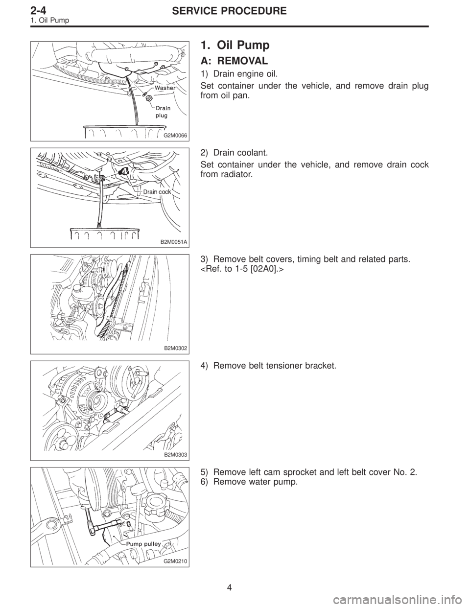
G2M0066
1. Oil Pump
A: REMOVAL
1) Drain engine oil.
Set container under the vehicle, and remove drain plug
from oil pan.
B2M0051A
2) Drain coolant.
Set container under the vehicle, and remove drain cock
from radiator.
B2M0302
3) Remove belt covers, timing belt and related parts.
B2M0303
4) Remove belt tensioner bracket.
G2M0210
5) Remove left cam sprocket and left belt cover No. 2.
6) Remove water pump.
4
2-4SERVICE PROCEDURE
1. Oil Pump
Page 119 of 2248
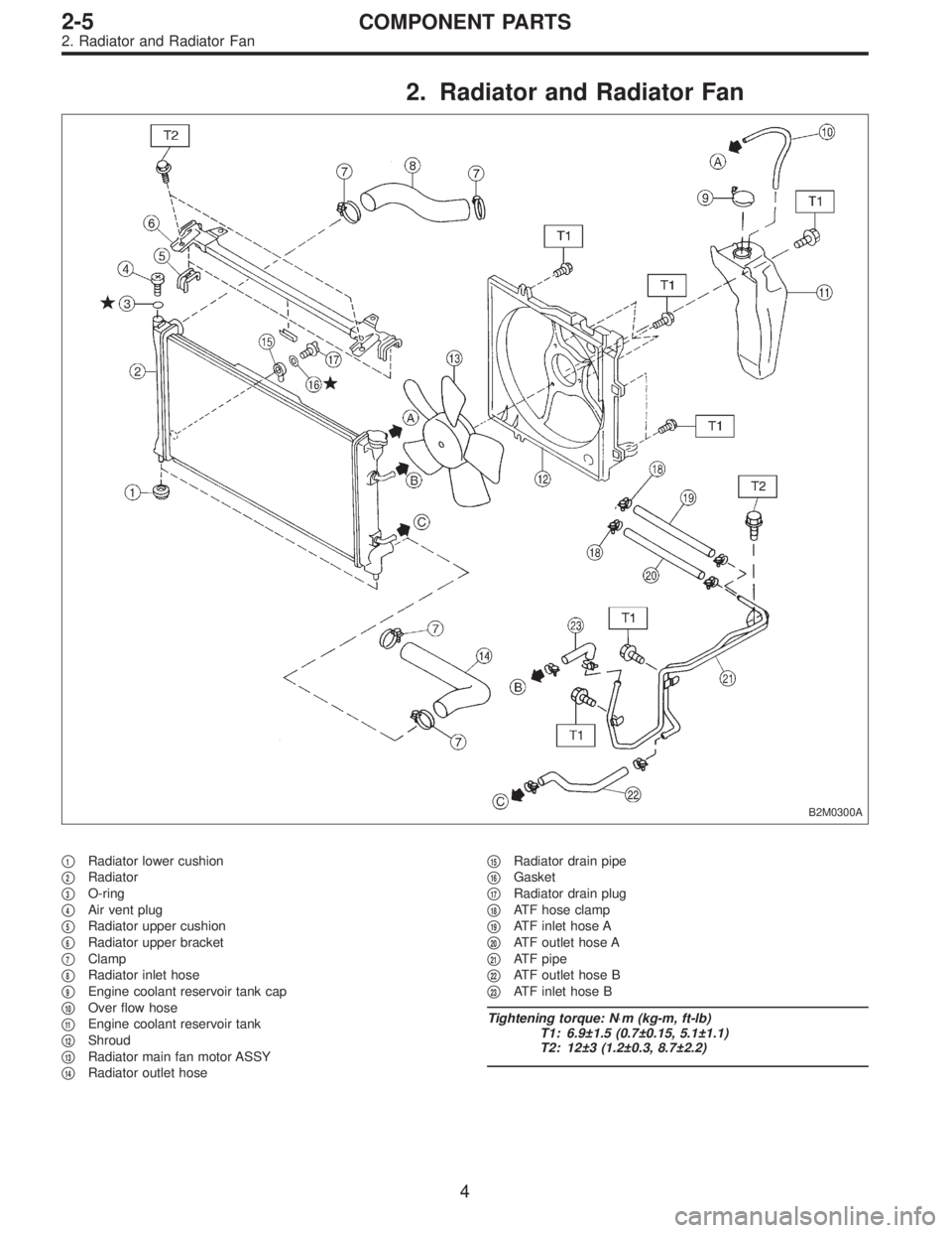
2. Radiator and Radiator Fan
B2M0300A
�1Radiator lower cushion
�
2Radiator
�
3O-ring
�
4Air vent plug
�
5Radiator upper cushion
�
6Radiator upper bracket
�
7Clamp
�
8Radiator inlet hose
�
9Engine coolant reservoir tank cap
�
10Over flow hose
�
11Engine coolant reservoir tank
�
12Shroud
�
13Radiator main fan motor ASSY
�
14Radiator outlet hose�
15Radiator drain pipe
�
16Gasket
�
17Radiator drain plug
�
18ATF hose clamp
�
19ATF inlet hose A
�
20ATF outlet hose A
�
21ATF pipe
�
22ATF outlet hose B
�
23ATF inlet hose B
Tightening torque: N⋅m (kg-m, ft-lb)
T1: 6.9±1.5 (0.7±0.15, 5.1±1.1)
T2: 12±3 (1.2±0.3, 8.7±2.2)
4
2-5COMPONENT PARTS
2. Radiator and Radiator Fan
Page 900 of 2248
B4M0101A
3) Disconnect the connection between the expansion
valve and pipe from receiver drier.
4) Remove the expansion valve from pipes.
5) To install expansion valve, reverse removal procedures.
Properly wrap capillary tube of expansion valve with seal.
6) Check to see if the evaporator fins are clogged. If they
are, clean them with compressed air.
CAUTION:
Water must never be used to clean the evaporator.
7) Check parts that have been removed for cracks or
scratches, and repair or replace them with new ones, if
necessary.
8) Reassemble the evaporator in the reverse order of dis-
assembly.
NOTE:
Confirm that the O-ring is inserted in the specified position.
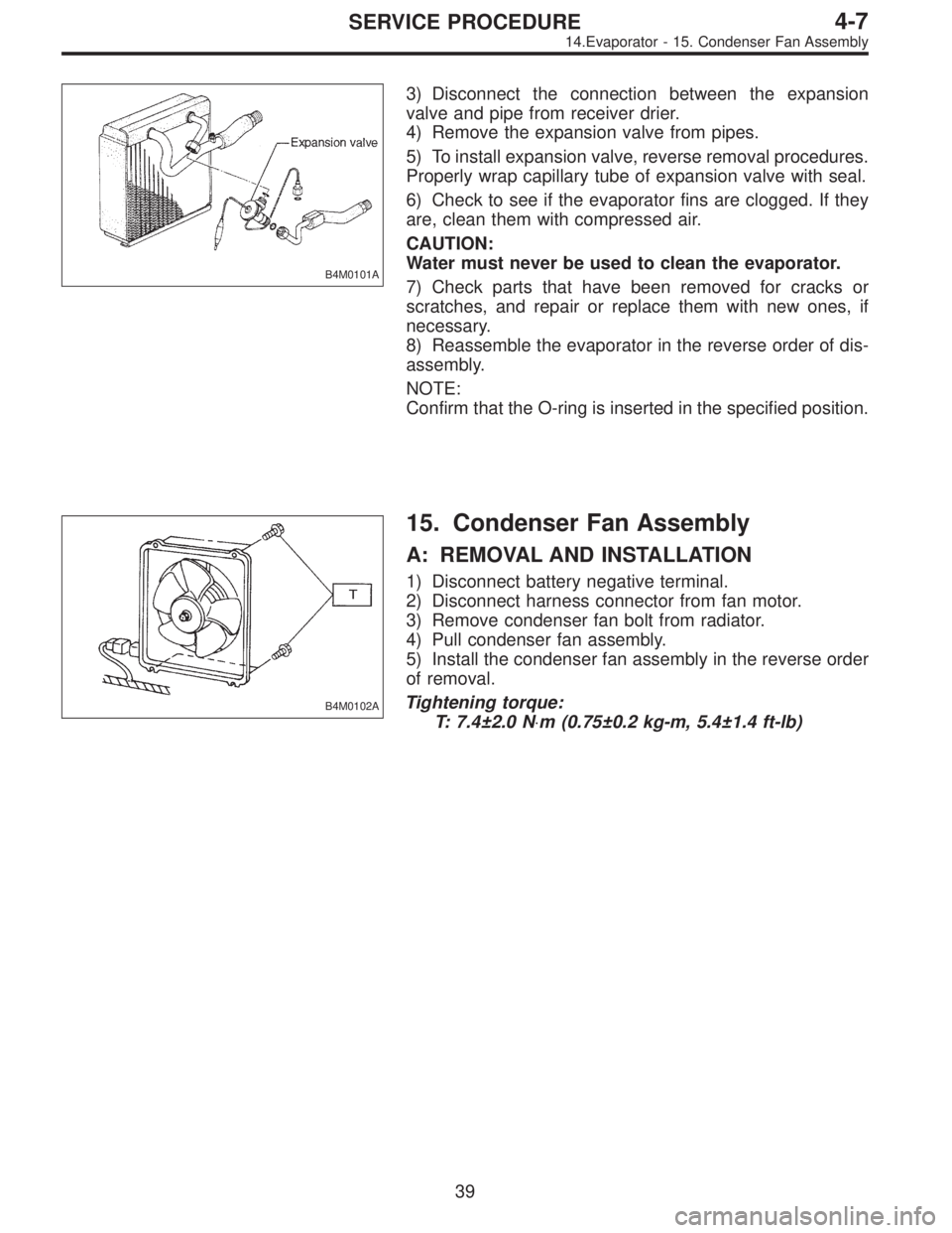
B4M0102A
15. Condenser Fan Assembly
A: REMOVAL AND INSTALLATION
1) Disconnect battery negative terminal.
2) Disconnect harness connector from fan motor.
3) Remove condenser fan bolt from radiator.
4) Pull condenser fan assembly.
5) Install the condenser fan assembly in the reverse order
of removal.
Tightening torque:
T: 7.4±2.0 N⋅m (0.75±0.2 kg-m, 5.4±1.4 ft-lb)
39
4-7SERVICE PROCEDURE
14.Evaporator - 15. Condenser Fan Assembly
Page 901 of 2248
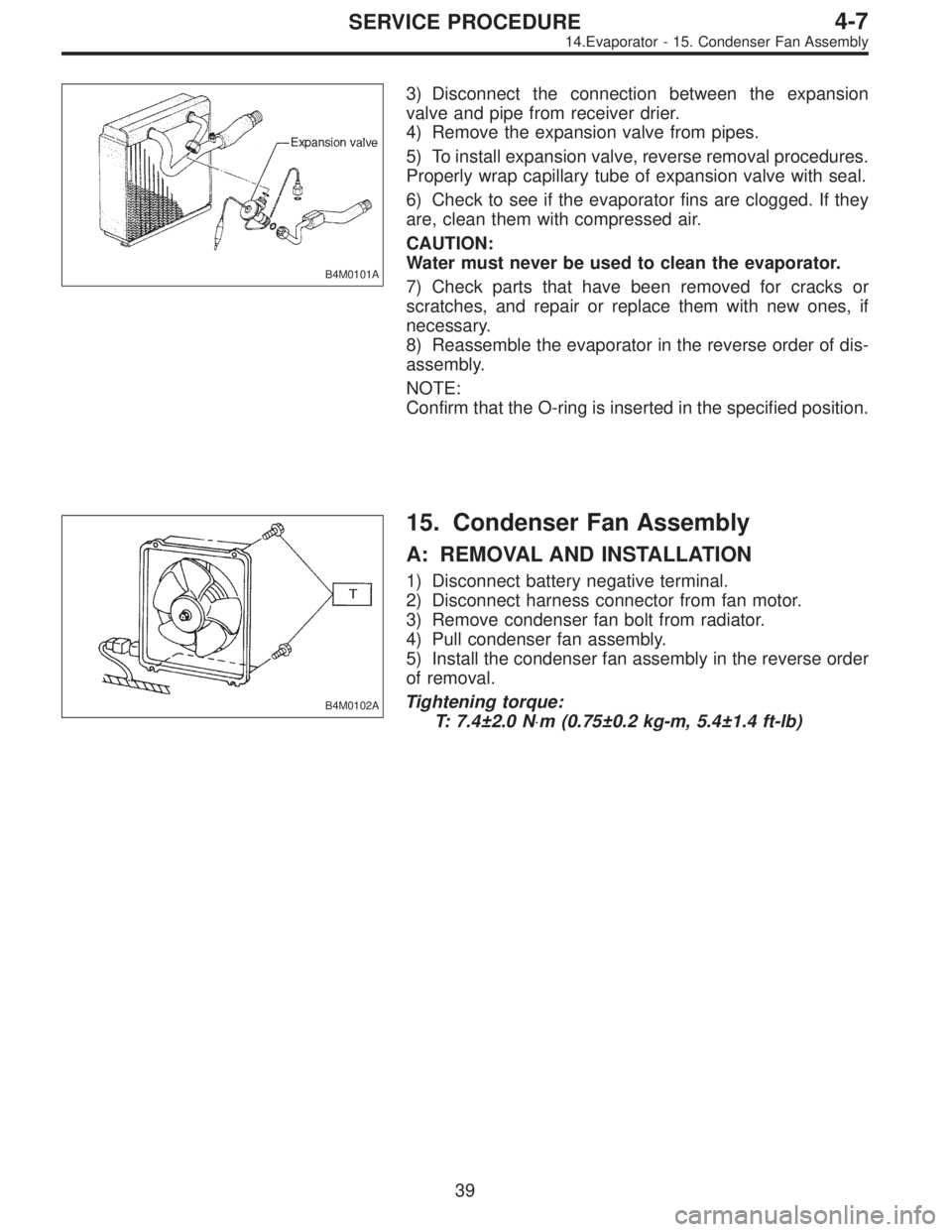
B4M0101A
3) Disconnect the connection between the expansion
valve and pipe from receiver drier.
4) Remove the expansion valve from pipes.
5) To install expansion valve, reverse removal procedures.
Properly wrap capillary tube of expansion valve with seal.
6) Check to see if the evaporator fins are clogged. If they
are, clean them with compressed air.
CAUTION:
Water must never be used to clean the evaporator.
7) Check parts that have been removed for cracks or
scratches, and repair or replace them with new ones, if
necessary.
8) Reassemble the evaporator in the reverse order of dis-
assembly.
NOTE:
Confirm that the O-ring is inserted in the specified position.
B4M0102A
15. Condenser Fan Assembly
A: REMOVAL AND INSTALLATION
1) Disconnect battery negative terminal.
2) Disconnect harness connector from fan motor.
3) Remove condenser fan bolt from radiator.
4) Pull condenser fan assembly.
5) Install the condenser fan assembly in the reverse order
of removal.
Tightening torque:
T: 7.4±2.0 N⋅m (0.75±0.2 kg-m, 5.4±1.4 ft-lb)
39
4-7SERVICE PROCEDURE
14.Evaporator - 15. Condenser Fan Assembly
Page 949 of 2248
G5M0141
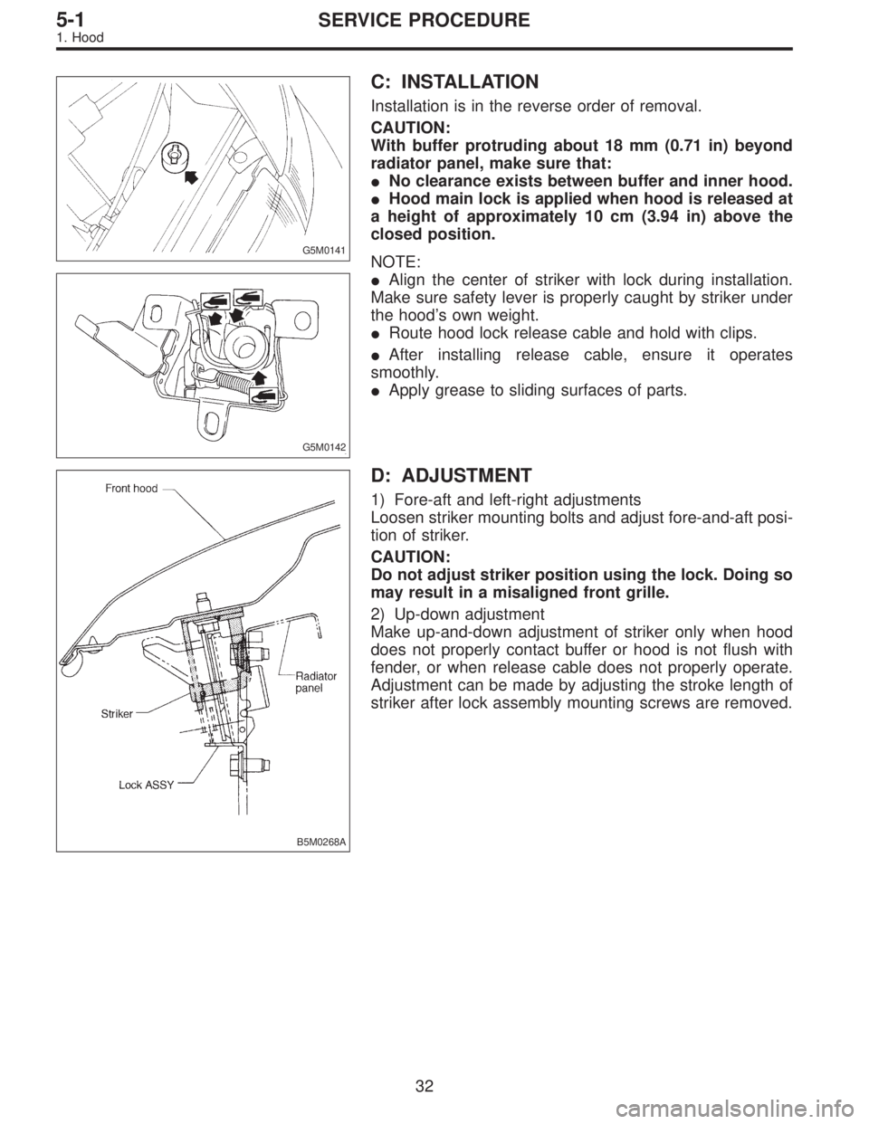
C: INSTALLATION
Installation is in the reverse order of removal.
CAUTION:
With buffer protruding about 18 mm (0.71 in) beyond
radiator panel, make sure that:
�No clearance exists between buffer and inner hood.
�Hood main lock is applied when hood is released at
a height of approximately 10 cm (3.94 in) above the
closed position.
G5M0142
NOTE:
�Align the center of striker with lock during installation.
Make sure safety lever is properly caught by striker under
the hood’s own weight.
�Route hood lock release cable and hold with clips.
�After installing release cable, ensure it operates
smoothly.
�Apply grease to sliding surfaces of parts.
B5M0268A
D: ADJUSTMENT
1) Fore-aft and left-right adjustments
Loosen striker mounting bolts and adjust fore-and-aft posi-
tion of striker.
CAUTION:
Do not adjust striker position using the lock. Doing so
may result in a misaligned front grille.
2) Up-down adjustment
Make up-and-down adjustment of striker only when hood
does not properly contact buffer or hood is not flush with
fender, or when release cable does not properly operate.
Adjustment can be made by adjusting the stroke length of
striker after lock assembly mounting screws are removed.
32
5-1SERVICE PROCEDURE
1. Hood
Page 1538 of 2248
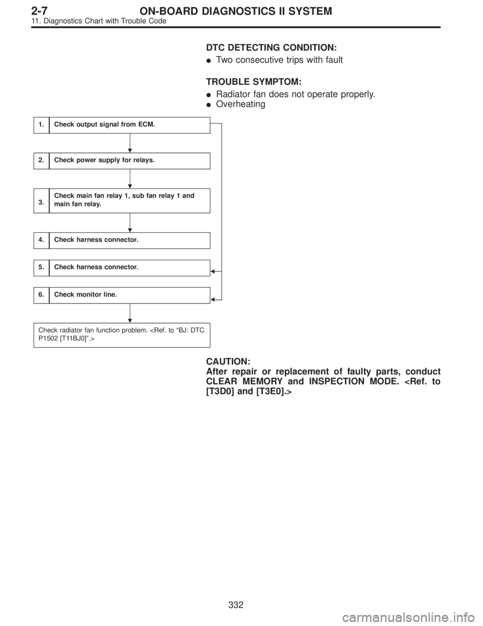
DTC DETECTING CONDITION:
�Two consecutive trips with fault
TROUBLE SYMPTOM:
�Radiator fan does not operate properly.
�Overheating
1.Check output signal from ECM.
�
�
2.Check power supply for relays.
3.Check main fan relay 1, sub fan relay 1 and
main fan relay.
4.Check harness connector.
5.Check harness connector.
6.Check monitor line.
Check radiator fan function problem.
P1502 [T11BJ0]”.>
CAUTION:
After repair or replacement of faulty parts, conduct
CLEAR MEMORY and INSPECTION MODE.
[T3D0] and [T3E0].>
�
�
�
�
332
2-7ON-BOARD DIAGNOSTICS II SYSTEM
11. Diagnostics Chart with Trouble Code
Page 1897 of 2248
3. Working Precautions
1. PRECAUTIONS WHEN WORKING WITH THE
PARTS MOUNTED ON THE VEHICLE
1) When working under a vehicle which is jacked-up,
always be sure to use safety stands.
2) The parking brake must always be applied during work-
ing. Also, in automatic transmission vehicles, keep the
select lever set to the P (Parking) range.
3) Be sure the workshop is properly ventilated when run-
ning the engine. Further, be careful not to touch the belt or
fan while the engine is operating.
4) Be careful not to touch hot metal parts, especially the
radiator and exhaust system immediately after the engine
has been shut off.
2. PRECAUTIONS IN TROUBLE DIAGNOSIS AND
REPAIR OF ELECTRIC PARTS
1) The battery cable must be disconnected from the bat-
tery’s () terminal, and the ignition switch must be set to the
OFF position, unless otherwise required by the diagnos-
tics.
2) Securely fasten the wiring harness with clamps and
slips so that the harness does not interfere with the body
end parts or edges and bolts or screws.
3) When installing parts, be careful not to catch them on
the wiring harness.
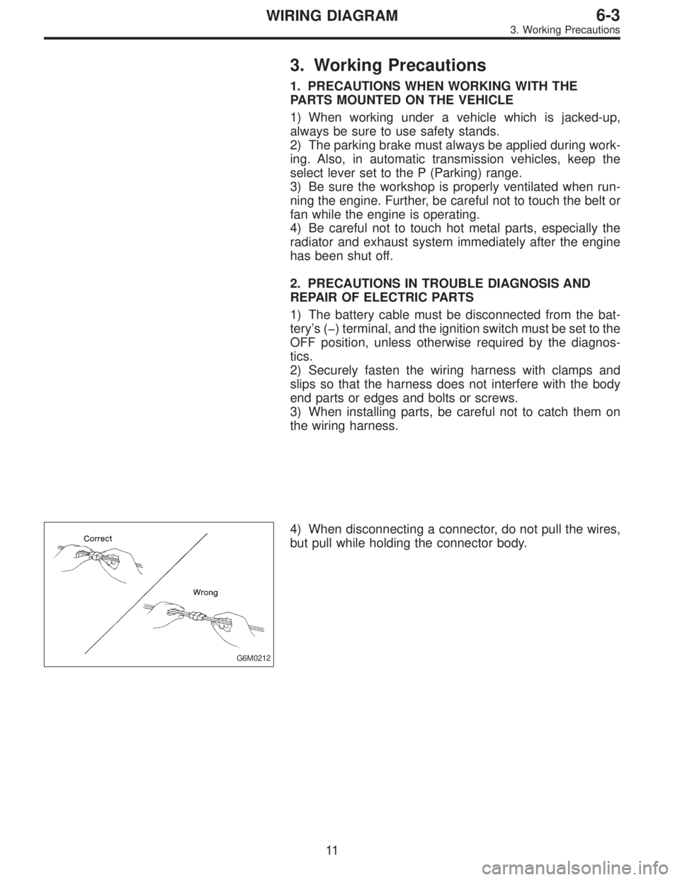
G6M0212
4) When disconnecting a connector, do not pull the wires,
but pull while holding the connector body.
11
6-3WIRING DIAGRAM
3. Working Precautions
Page 1997 of 2248
3. Working Precautions
1. PRECAUTIONS WHEN WORKING WITH THE
PARTS MOUNTED ON THE VEHICLE
1) When working under a vehicle which is jacked-up,
always be sure to use safety stands.
2) The parking brake must always be applied during work-
ing. Also, in automatic transmission vehicles, keep the
select lever set to the P (Parking) range.
3) Be sure the workshop is properly ventilated when run-
ning the engine. Further, be careful not to touch the belt or
fan while the engine is operating.
4) Be careful not to touch hot metal parts, especially the
radiator and exhaust system immediately after the engine
has been shut off.
2. PRECAUTIONS IN TROUBLE DIAGNOSIS AND
REPAIR OF ELECTRIC PARTS
1) The battery cable must be disconnected from the bat-
tery’s () terminal, and the ignition switch must be set to the
OFF position, unless otherwise required by the diagnos-
tics.
2) Securely fasten the wiring harness with clamps and
slips so that the harness does not interfere with the body
end parts or edges and bolts or screws.
3) When installing parts, be careful not to catch them on
the wiring harness.
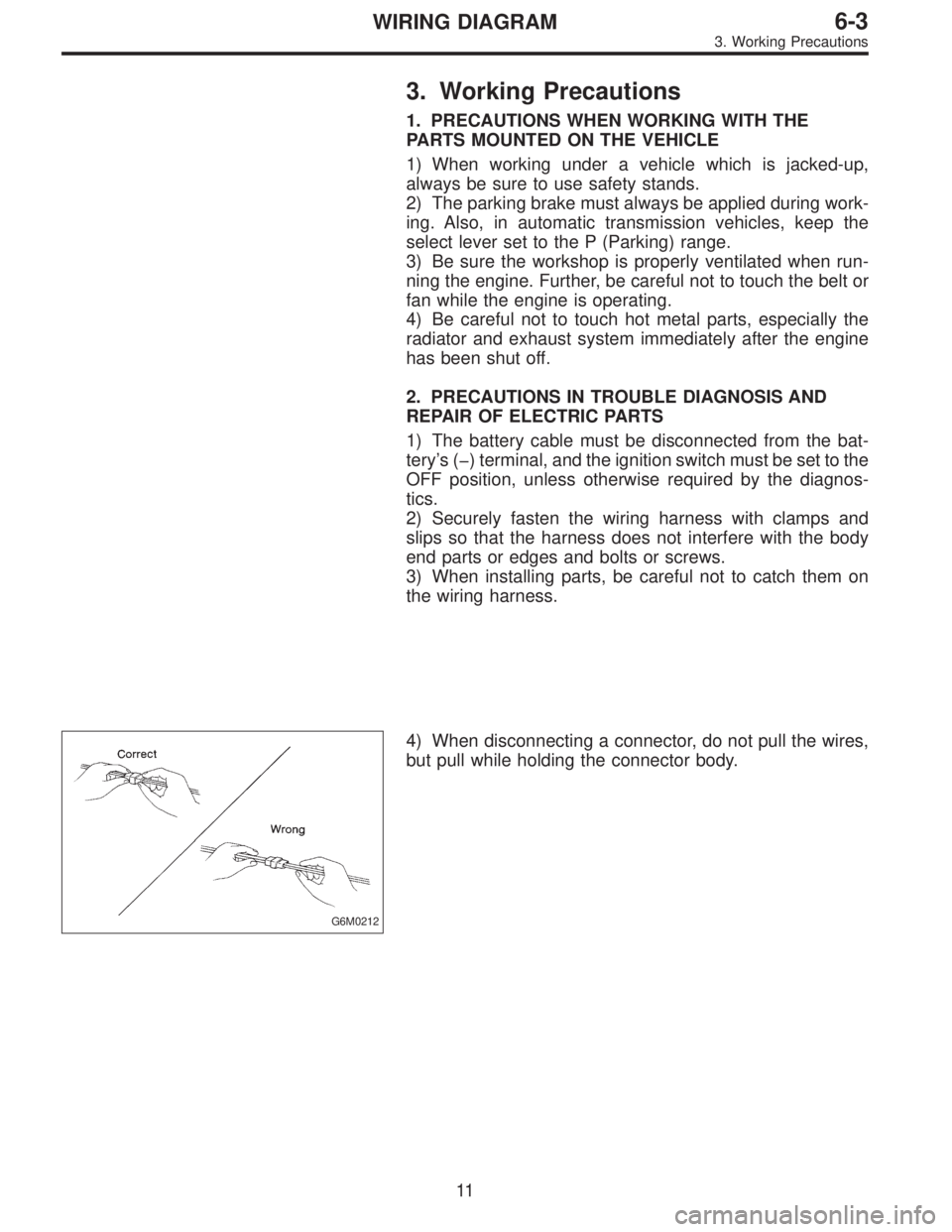
G6M0212
4) When disconnecting a connector, do not pull the wires,
but pull while holding the connector body.
11
6-3WIRING DIAGRAM
3. Working Precautions