Page 87 of 2248
H2M1707B
4) Installation of piston rings and oil ring
(1) Install oil ring spacer, upper rail and lower rail in this
order by hand. Then install second ring and top ring
with a piston ring expander.
(2) Position the top ring gap at A or B in the Figure.
(3) Position the second ring gap at 180°on the reverse
side for the top ring gap.
H2M1708B
(4) Position the upper rail gap at C or D in the Figure.
(5) Position the expander gap at 180°of the reverse
side for the upper rail gap.
(6) Position the lower rail gap at E or F in the Figure.
CAUTION:
�Ensure ring gaps do not face the same direction.
�Ensure ring gaps are not within the piston skirt area.
B2M1403A
5) Install circlip.
Install circlips in piston holes located opposite service
holes in cylinder block, when positioning all pistons in the
corresponding cylinders.
CAUTION:
Use new circlips.
NOTE:
Piston front mark“�”facer toward front of engine.
66
2-3SERVICE PROCEDURE
7. Cylinder Block
Page 199 of 2248
 Remove right rear wheel.
4) Open fuel filler flap and remove filler cap.
5) Remove screws holding packing in place.
G2M0361
6) Lift-up the vehicle.
7) Remove fuel filler pipe protector.
G2M")
G2M0360
3) Remove right rear wheel.
4) Open fuel filler flap and remove filler cap.
5) Remove screws holding packing in place.
G2M0361
6) Lift-up the vehicle.
7) Remove fuel filler pipe protector.
G2M0353
8) Remove clip, and separate air vent hose from pipe.
9) Loosen clamp, and separate fuel filler hose from pipe.
�
1Fuel filler hose
�
2Air vent hose
10) Remove fuel filler pipe to under side of the vehicle.
G2M0364
B: INSTALLATION
1) Hold fuel filler flap open.
2) Set fuel saucer�
1with rubber packing�3, and insert fuel
filler pipe into hole from the inner side of apron.
3) Align holes in fuel filler pipe neck and set cup�
2, and
tighten screws.
NOTE:
If edges of rubber packing are folded toward the inside,
straighten it with a screwdriver.
G2M0353
4) Insert fuel filler hose approximately 25 to 30 mm (0.98
to 1.18 in) over the lower end of fuel filler pipe and tighten
clamp.
�
1Fuel filler hose
�
2Air vent hose
CAUTION:
Do not allow clips to touch air vent hose and rear sus-
pension crossmember.
13
2-8SERVICE PROCEDURE
4. Fuel Filler Pipe
Page 267 of 2248
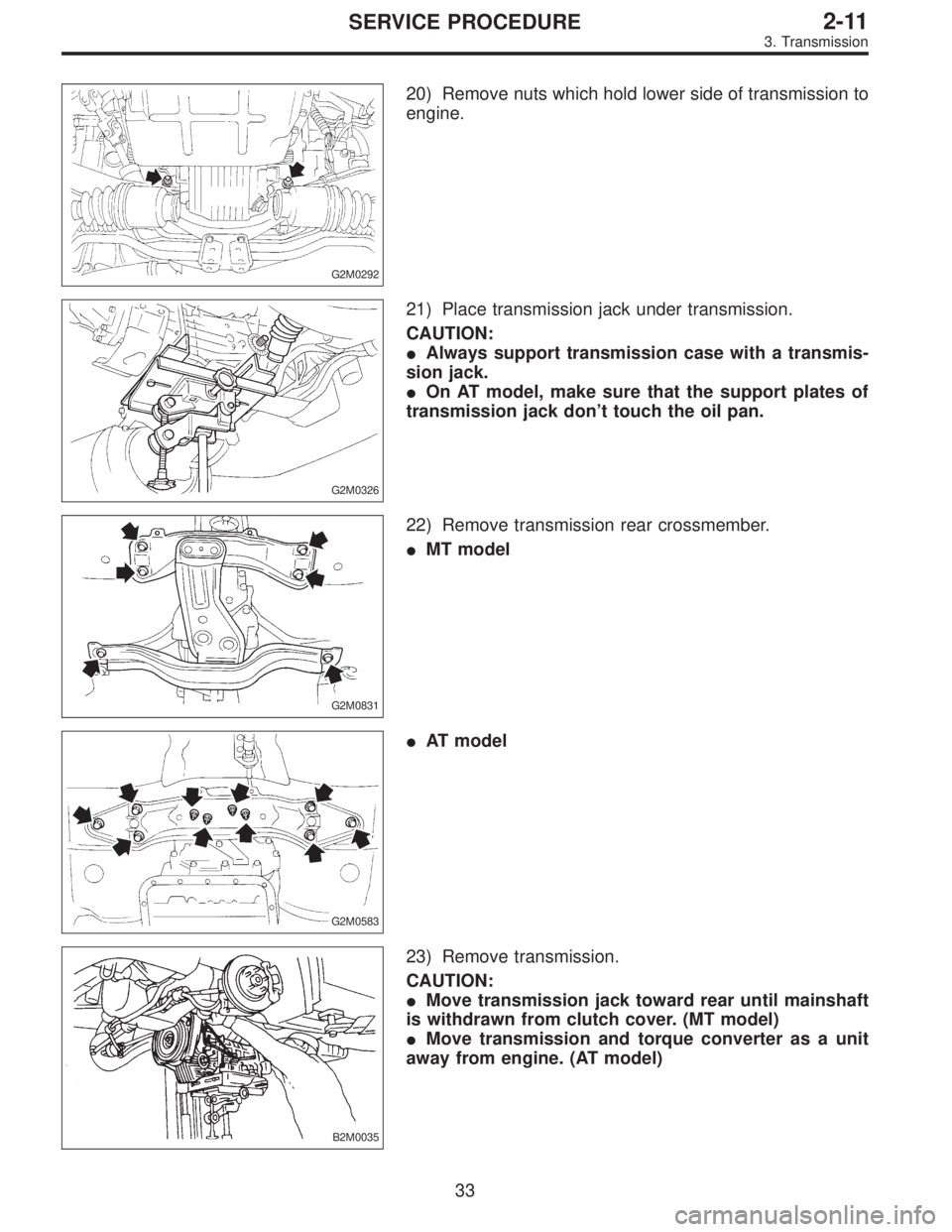
G2M0292
20) Remove nuts which hold lower side of transmission to
engine.
G2M0326
21) Place transmission jack under transmission.
CAUTION:
�Always support transmission case with a transmis-
sion jack.
�On AT model, make sure that the support plates of
transmission jack don’t touch the oil pan.
G2M0831
22) Remove transmission rear crossmember.
�MT model
G2M0583
�AT model
B2M0035
23) Remove transmission.
CAUTION:
�Move transmission jack toward rear until mainshaft
is withdrawn from clutch cover. (MT model)
�Move transmission and torque converter as a unit
away from engine. (AT model)
33
2-11SERVICE PROCEDURE
3. Transmission
Page 300 of 2248
 Assembly of reverse check sleeve
(1) Install reverse accent shaft�
F, check cam�D, re")
B3M0043A
2. TRANSFER CASE
Assembly of transfer case is in the reverse order of disas-
sembly. Do the following:
1) Assembly of reverse check sleeve
(1) Install reverse accent shaft�
F, check cam�D, return
spring�
Eand check spring�Conto reverse check
sleeve.
NOTE:
Be sure the bent section of reverse check spring is posi-
tioned in the groove in check cam.
(2) Hook the bent section of reverse check spring over
reverse check plate�
B.
(3) Rotate cam so that the protrusion of reverse check
cam is at the opening in plate.
(4) With cam held in that position, install plate onto
reverse check sleeve and hold with snap ring�
A(Inner-
28).
(5) Position O-ring�
G(35.4 x 1.5) in groove in sleeve.
B3M0048A
CAUTION:
�Make sure the cutout section of reverse accent shaft
is aligned with the opening in reverse check sleeve.
�Spin cam by hand for smooth rotation.
If it does not return properly, replace reverse check
spring.
�Move cam and shaft all the way toward plate and
release.
If cam does not return properly, replace reverse check
spring; if shaft does not, check for scratches on the
inner surface of sleeve. If sleeve is in good order,
replace spring.
�Select a suitable reverse accent shaft and reverse
check plate by referring to “Neutral Position Adjust-
ment.”
25
3-1SERVICE PROCEDURE
2. Transfer Case and Extension (AWD Model)
Page 303 of 2248

T1: 15.7±1.5 (1.6±0.15, 11.6±1.1)
T2: 19.6±1.5 (2.00±0.15, 14.5±1.1)
T3: 24.5±2.0 (2.50±0.20, 18.1±1.4)
1) Install transfer cas")
D: INSTALLATION
B3M0053A
Tightening torque: N⋅m (kg-m, ft-lb)
T1: 15.7±1.5 (1.6±0.15, 11.6±1.1)
T2: 19.6±1.5 (2.00±0.15, 14.5±1.1)
T3: 24.5±2.0 (2.50±0.20, 18.1±1.4)
1) Install transfer case�2with extension assembly�1.
2) Secure selector arm to shifter arm with shifter fork
screw�
3. Shifter arm should be caught by pawl of rod.
Selector arm must be engaged with reverse check sleeve
assembly.
3) Adjustment of neutral position
(1) Shift gear into 3rd gear position.
(2) Shifter arm turns lightly toward the 1st/2nd gear
side but heavily toward the reverse gear side because
of the function of the return spring, until arm contacts
the stopper.
(3) Make adjustment so that the heavy stroke (reverse
side) is a little more than the light stroke (1st/2nd side).
(4) To adjust, remove bolts holding reverse check
sleeve assembly�
4to the case, move sleeve assem-
bly outward, and place adjustment shim (0 to 1 ea.)
between sleeve assembly and case to adjust the clear-
ance.
CAUTION:
Be careful not to break O-ring when placing shim(s).
Adjustment shim
Part No. Thickness mm (in)
32190AA000 0.15 (0.0059)
32190AA010 0.30 (0.0118)
28
3-1SERVICE PROCEDURE
2. Transfer Case and Extension (AWD Model)
Page 306 of 2248
 Assembly of rear case is in the reverse order of disas-
sembly.
G3M0952
Tightening torque: N⋅m (kg-m, ft-lb)
T1: 6.4±0.5 (0.65±0.05, 4.7±0.4)
T2: 10±1 (1.0±0.1, 7.2±0.7)
T3: 25�")
B: ASSEMBLY
1) Assembly of rear case is in the reverse order of disas-
sembly.
G3M0952
Tightening torque: N⋅m (kg-m, ft-lb)
T1: 6.4±0.5 (0.65±0.05, 4.7±0.4)
T2: 10±1 (1.0±0.1, 7.2±0.7)
T3: 25±5 (2.5±0.5, 18.1±3.6)
2) Installation of shifter arm�6
Install shifter arm into the partition from the front while
inserting selector arm into the opening in reverse check
sleeve. Pass shaft through hole in selector arm until its end
comes out of the rear of transmission case assembly.
CAUTION:
Apply a coat of gear oil to shifter arm. Also make sure
oil seal is positioned properly.
3) Adjustment of neutral position
NOTE:
After assembling and installing rear case, adjust neutral
position.
(1) Shift gear into 3rd gear position.
(2) Shifter arm turns lightly toward the 1st/2nd gear
side but heavily toward the reverse gear side because
of the function of the return spring, until arm contacts
the stopper.
(3) Make adjustment so that the heavy stroke (reverse
side) is a little more than the light stroke (1st/2nd side).
(4) To adjust, remove bolts holding reverse check
sleeve assembly to the case, move sleeve assembly
outward, and place adjustment shim (0 to 1 ea.)
between sleeve assembly and case to adjust the clear-
ance.
31
3-1SERVICE PROCEDURE
3. Rear Case (FWD Model)
Page 311 of 2248
 Drive out spring pin�6, and pull out 3-4 fork rod�7and
shifter fork�
8.
NOTE:
When removing rod, keep other rods in neutral. Also, when
pulling out straight pin, remove it toward inside of")
B3M0333B
3) Drive out spring pin�6, and pull out 3-4 fork rod�7and
shifter fork�
8.
NOTE:
When removing rod, keep other rods in neutral. Also, when
pulling out straight pin, remove it toward inside of case so
that it may not hit against case.
4) Drive out straight pin�
9, and pull out 1-2 fork rod�10and
shifter fork�
11.
G3M0602
5) Pull out straight pin�12, and remove idler gear shaft�13,
reverse idler gear�
14and washer�15.
6) Remove outer snap ring�
16, and pull out reverse shifter
rod arm�
17from reverse fork rod�18. Then take out ball,
spring and interlock plunger from rod.
And then remove rod.
NOTE:
When pulling out reverse shifter rod arm, be careful not to
let ball pop out of arm.
7) Remove reverse shifter lever�
19.
G3M0546
8) Remove differential side retainers using ST.
ST 499787000 WRENCH ASSY
G3M0547
9) Remove outer snap ring�20and pull out speedometer
driven gear�
21. Next, remove vehicle speed sensor 2, oil
seal, speedometer shaft�
22and washer.
36
3-1SERVICE PROCEDURE
4. Transmission Case
Page 313 of 2248
3) Install reverse arm fork spring, ball and interlock
plunger (5.56 x 19.6) to reverse fork rod arm�
5. Insert
reverse fork rod�
6into hole in reverse fork rod arm�5, and
hold it with outer snap ring�
7using ST.
ST 399411700 ACCENT BALL INSTALLER
CAUTION:
Apply grease to plunger to prevent it from falling.
4) Position ball�
8(7.1438), spring�9and gasket�10in
reverse shifter rod hole, on left side transmission case, and
tighten checking ball plug�
11.
CAUTION:
Replace gasket with a new one.
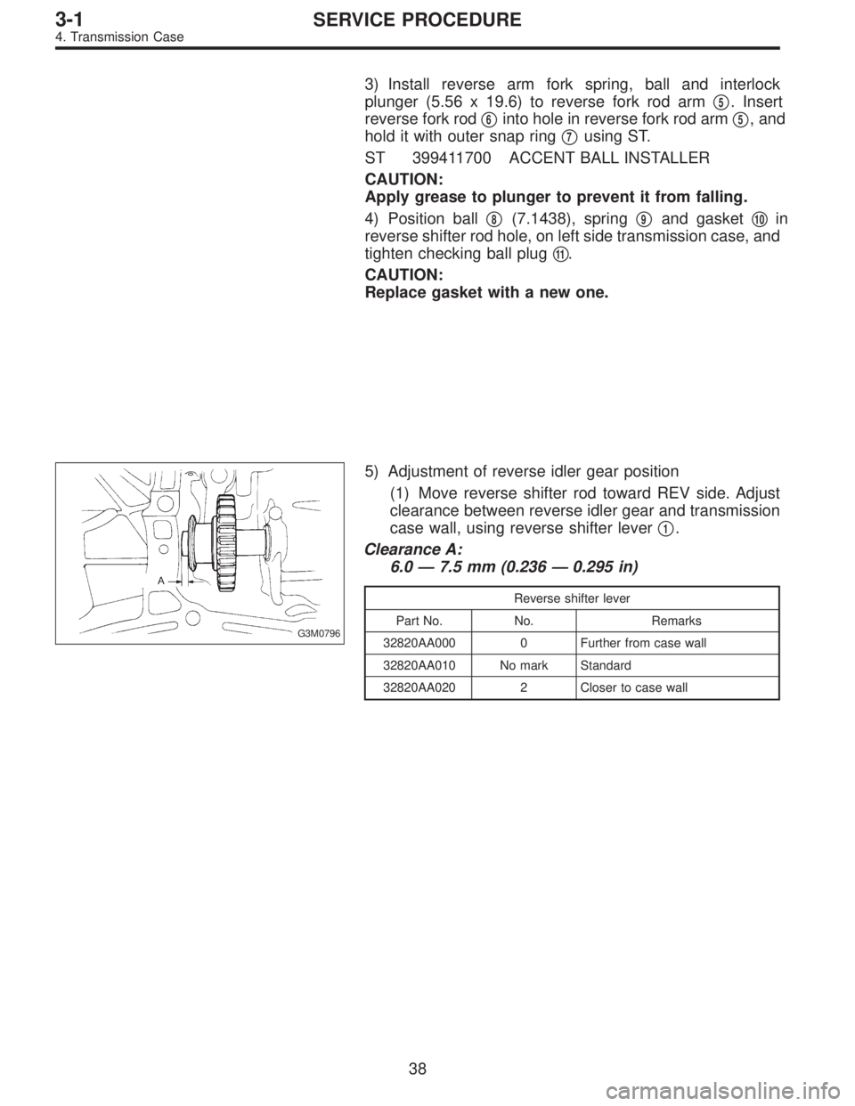
G3M0796
5) Adjustment of reverse idler gear position
(1) Move reverse shifter rod toward REV side. Adjust
clearance between reverse idler gear and transmission
case wall, using reverse shifter lever�
1.
Clearance A:
6.0—7.5 mm (0.236—0.295 in)
Reverse shifter lever
Part No. No. Remarks
32820AA000 0 Further from case wall
32820AA010 No mark Standard
32820AA020 2 Closer to case wall
38
3-1SERVICE PROCEDURE
4. Transmission Case
 Installation of piston rings and oil ring
(1) Install oil ring spacer, upper rail and lower rail in this
order by hand. Then install second ring and top ring
with a piston ring expander.
(")