Page 672 of 2248
G4M0828
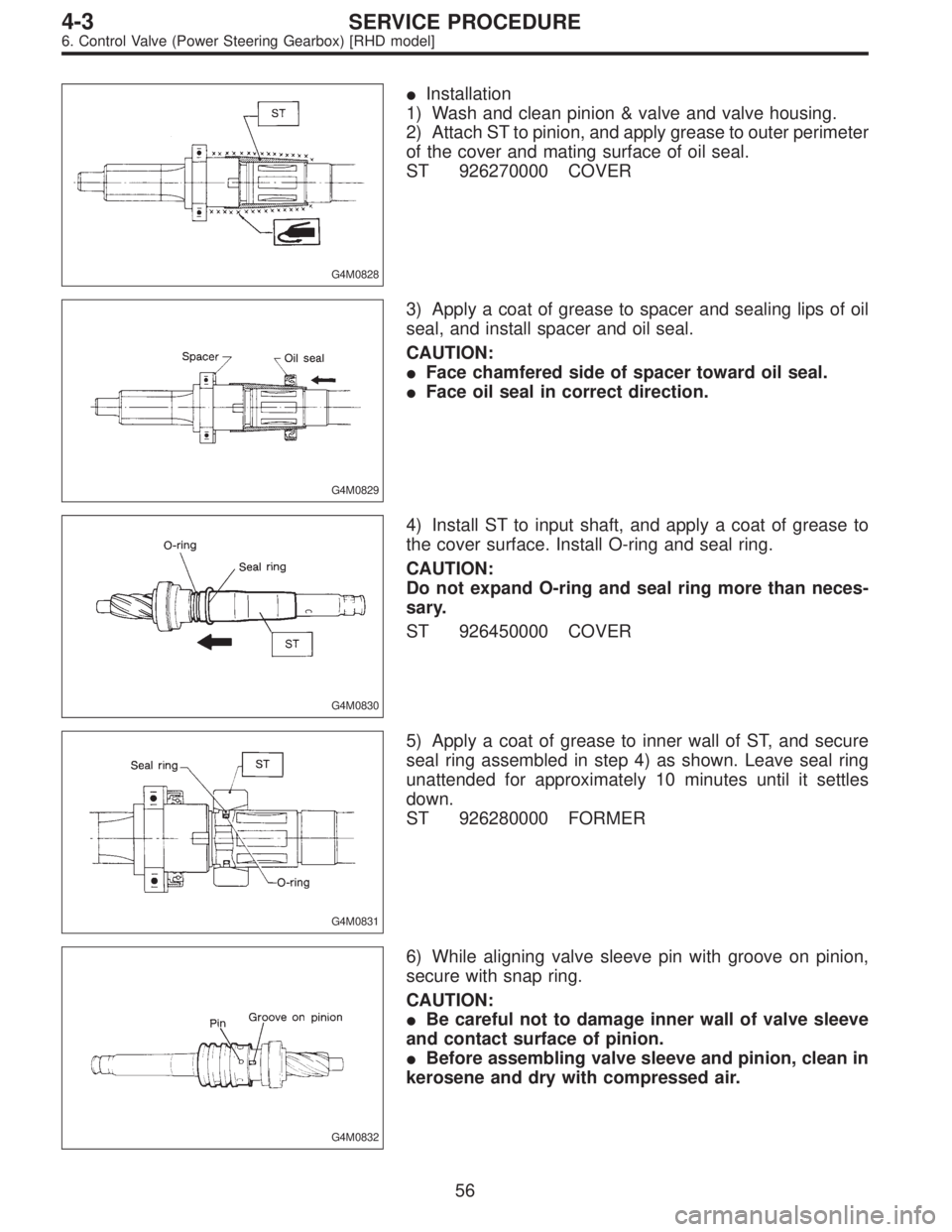
�Installation
1) Wash and clean pinion & valve and valve housing.
2) Attach ST to pinion, and apply grease to outer perimeter
of the cover and mating surface of oil seal.
ST 926270000 COVER
G4M0829
3) Apply a coat of grease to spacer and sealing lips of oil
seal, and install spacer and oil seal.
CAUTION:
�Face chamfered side of spacer toward oil seal.
�Face oil seal in correct direction.
G4M0830
4) Install ST to input shaft, and apply a coat of grease to
the cover surface. Install O-ring and seal ring.
CAUTION:
Do not expand O-ring and seal ring more than neces-
sary.
ST 926450000 COVER
G4M0831
5) Apply a coat of grease to inner wall of ST, and secure
seal ring assembled in step 4) as shown. Leave seal ring
unattended for approximately 10 minutes until it settles
down.
ST 926280000 FORMER
G4M0832
6) While aligning valve sleeve pin with groove on pinion,
secure with snap ring.
CAUTION:
�Be careful not to damage inner wall of valve sleeve
and contact surface of pinion.
�Before assembling valve sleeve and pinion, clean in
kerosene and dry with compressed air.
56
4-3SERVICE PROCEDURE
6. Control Valve (Power Steering Gearbox) [RHD model]
Page 694 of 2248
E: ASSEMBLY
1) Reassembly precautions
(1) Whenever O-rings, oil seals, and snap rings are
removed, they must be replaced with new ones.
(2) Thoroughly wash parts and allow to dry. They must
be kept free from cleaning oil and dust.
(3) Reassembly procedure must be performed in clean
place. Ensure that parts are kept away from waste
threads or other dust particles.
(4) Cleaning oil tends to stay inside the front casing.
Remove it completely by blowing compressed air.
(5) Ensure that parts are free from rust. (Use specified
hydraulic oil for rust prevention after cleaning and dry-
ing.)
(6) Reverse the sequence of disassembly procedures.
2) Shaft
(1) Apply grease to oil seal and inner surface of front
casing (at bearing location).
CAUTION:
Make sure that the front body internal surfaces are free
from damage.
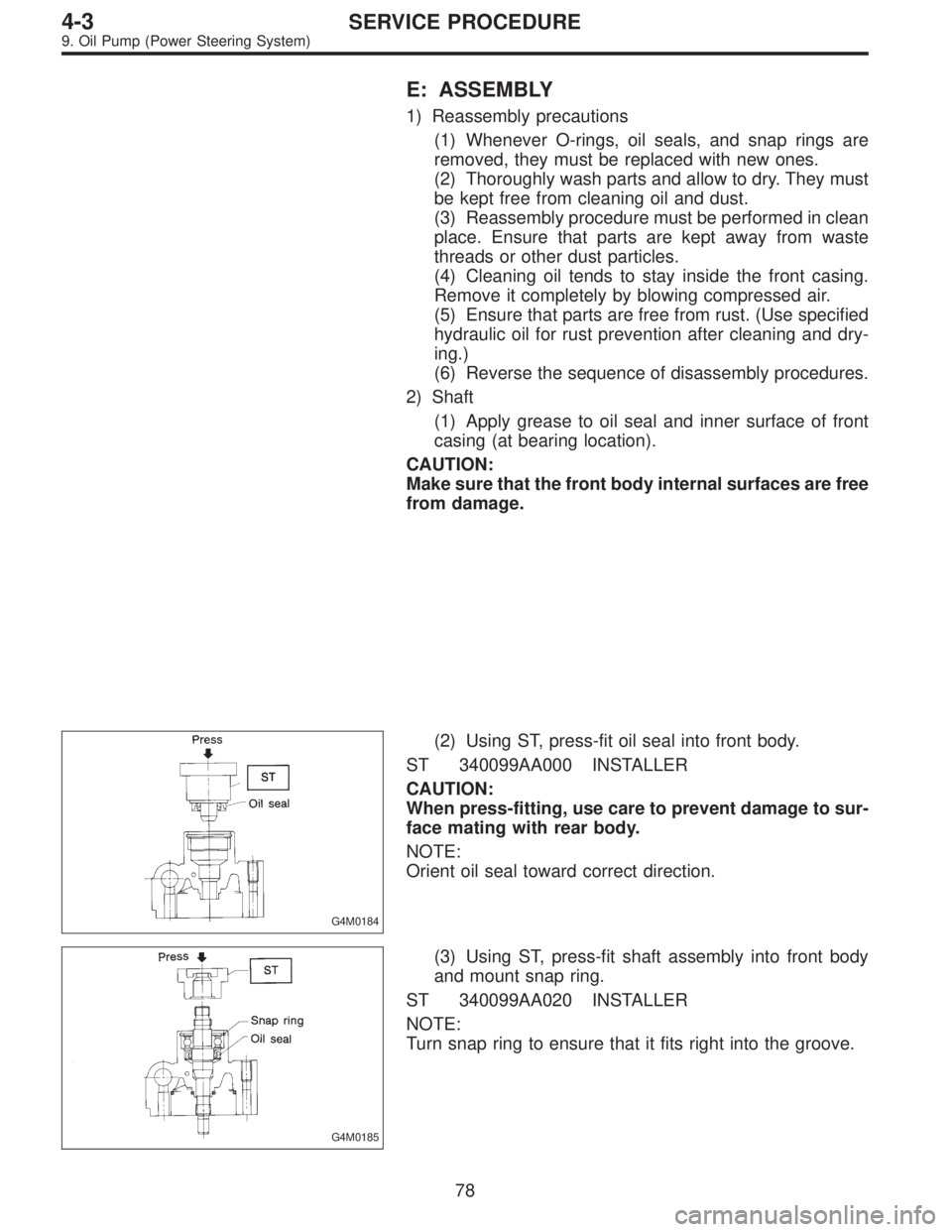
G4M0184
(2) Using ST, press-fit oil seal into front body.
ST 340099AA000 INSTALLER
CAUTION:
When press-fitting, use care to prevent damage to sur-
face mating with rear body.
NOTE:
Orient oil seal toward correct direction.
G4M0185
(3) Using ST, press-fit shaft assembly into front body
and mount snap ring.
ST 340099AA020 INSTALLER
NOTE:
Turn snap ring to ensure that it fits right into the groove.
78
4-3SERVICE PROCEDURE
9. Oil Pump (Power Steering System)
Page 695 of 2248
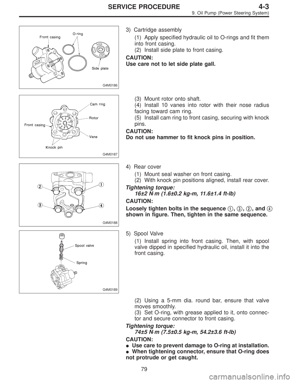
G4M0186
3) Cartridge assembly
(1) Apply specified hydraulic oil to O-rings and fit them
into front casing.
(2) Install side plate to front casing.
CAUTION:
Use care not to let side plate gall.
G4M0187
(3) Mount rotor onto shaft.
(4) Install 10 vanes into rotor with their nose radius
facing toward cam ring.
(5) Install cam ring to front casing, securing with knock
pins.
CAUTION:
Do not use hammer to fit knock pins in position.
G4M0188
4) Rear cover
(1) Mount seal washer on front casing.
(2) With knock pin positions aligned, install rear cover.
Tightening torque:
16±2 N⋅m (1.6±0.2 kg-m, 11.6±1.4 ft-lb)
CAUTION:
Loosely tighten bolts in the sequence�
1,�3,�2, and�4
shown in figure. Then, tighten in the same sequence.
G4M0189
5) Spool Valve
(1) Install spring into front casing. Then, with spool
valve dipped in specified hydraulic oil, install it into the
front casing.
(2) Using a 5-mm dia. round bar, ensure that valve
moves smoothly.
(3) Set O-ring, with grease applied to it, onto connec-
tor and secure connector to front casing.
Tightening torque:
74±5 N⋅m (7.5±0.5 kg-m, 54.2±3.6 ft-lb)
CAUTION:
�Use care to prevent damage to O-ring at installation.
�When tightening connector, ensure that O-ring does
not protrude or get caught.
79
4-3SERVICE PROCEDURE
9. Oil Pump (Power Steering System)
Page 736 of 2248
G4M0365
3) Measure disc rotor thickness.
NOTE:
Make sure that micrometer is set 5 mm (0.20 in) inward of
rotor outer perimeter.
Disc rotor thickness A
mm (in)Standard
valueService
limitDisc outer dia.
24.0
(0.945)22.0
(0.866)260
(10.24)
G4M0503
B: REMOVAL
1) Remove union bolt and disconnect brake hose from
caliper body assembly.
G4M0366
2) Loosen lock pin.
G4M0367
3) Raise caliper body and move it toward vehicle center to
separate it from support.
G4M0368
4) Remove support from housing.
NOTE:
Remove support only when replacing it or the rotor. It need
not be removed when servicing caliper body assembly.
21
4-4SERVICE PROCEDURE
1. Front Disc Brake
Page 742 of 2248
G4M0382
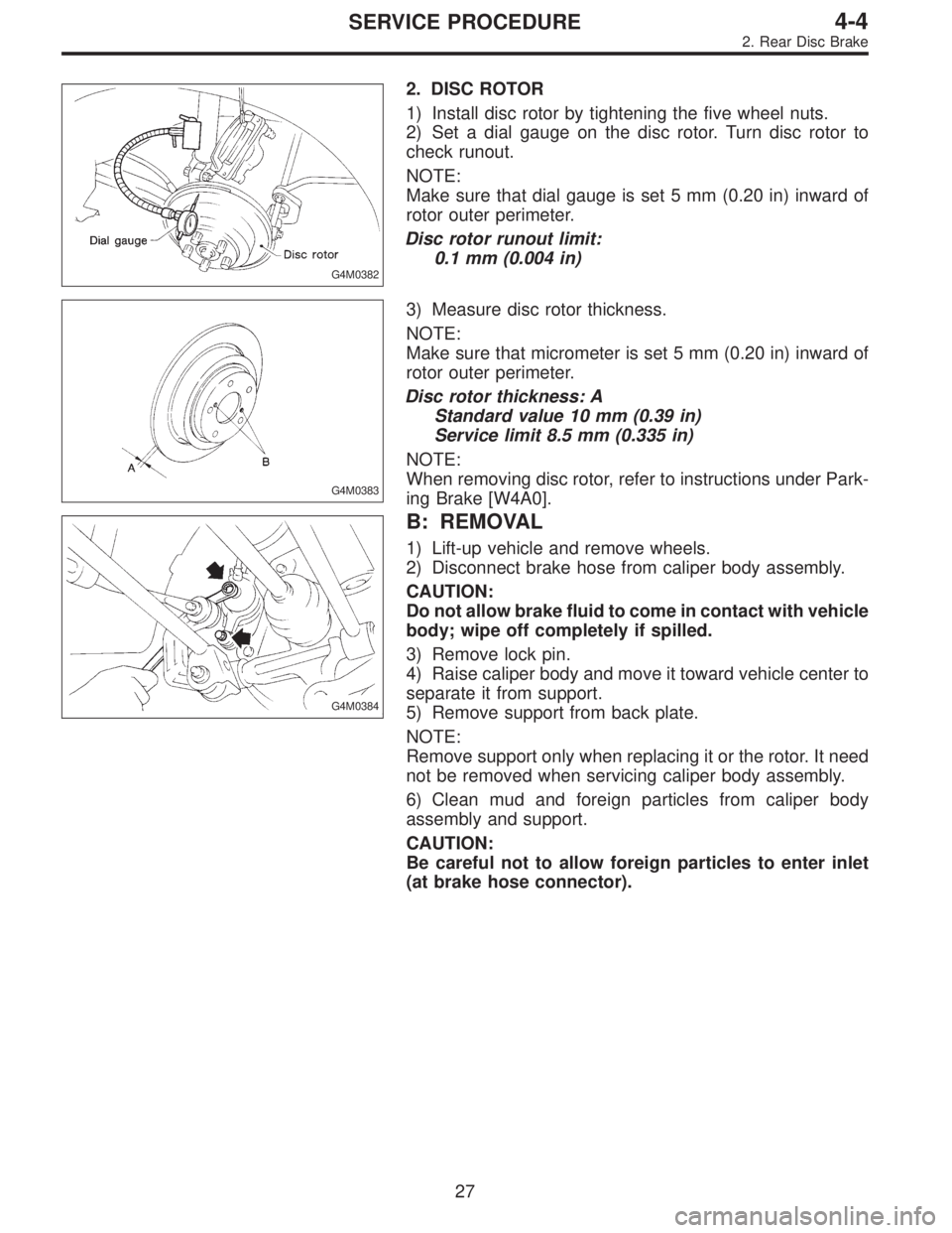
2. DISC ROTOR
1) Install disc rotor by tightening the five wheel nuts.
2) Set a dial gauge on the disc rotor. Turn disc rotor to
check runout.
NOTE:
Make sure that dial gauge is set 5 mm (0.20 in) inward of
rotor outer perimeter.
Disc rotor runout limit:
0.1 mm (0.004 in)
G4M0383
3) Measure disc rotor thickness.
NOTE:
Make sure that micrometer is set 5 mm (0.20 in) inward of
rotor outer perimeter.
Disc rotor thickness: A
Standard value 10 mm (0.39 in)
Service limit 8.5 mm (0.335 in)
NOTE:
When removing disc rotor, refer to instructions under Park-
ing Brake [W4A0].
G4M0384
B: REMOVAL
1) Lift-up vehicle and remove wheels.
2) Disconnect brake hose from caliper body assembly.
CAUTION:
Do not allow brake fluid to come in contact with vehicle
body; wipe off completely if spilled.
3) Remove lock pin.
4) Raise caliper body and move it toward vehicle center to
separate it from support.
5) Remove support from back plate.
NOTE:
Remove support only when replacing it or the rotor. It need
not be removed when servicing caliper body assembly.
6) Clean mud and foreign particles from caliper body
assembly and support.
CAUTION:
Be careful not to allow foreign particles to enter inlet
(at brake hose connector).
27
4-4SERVICE PROCEDURE
2. Rear Disc Brake
Page 761 of 2248
G4M0744
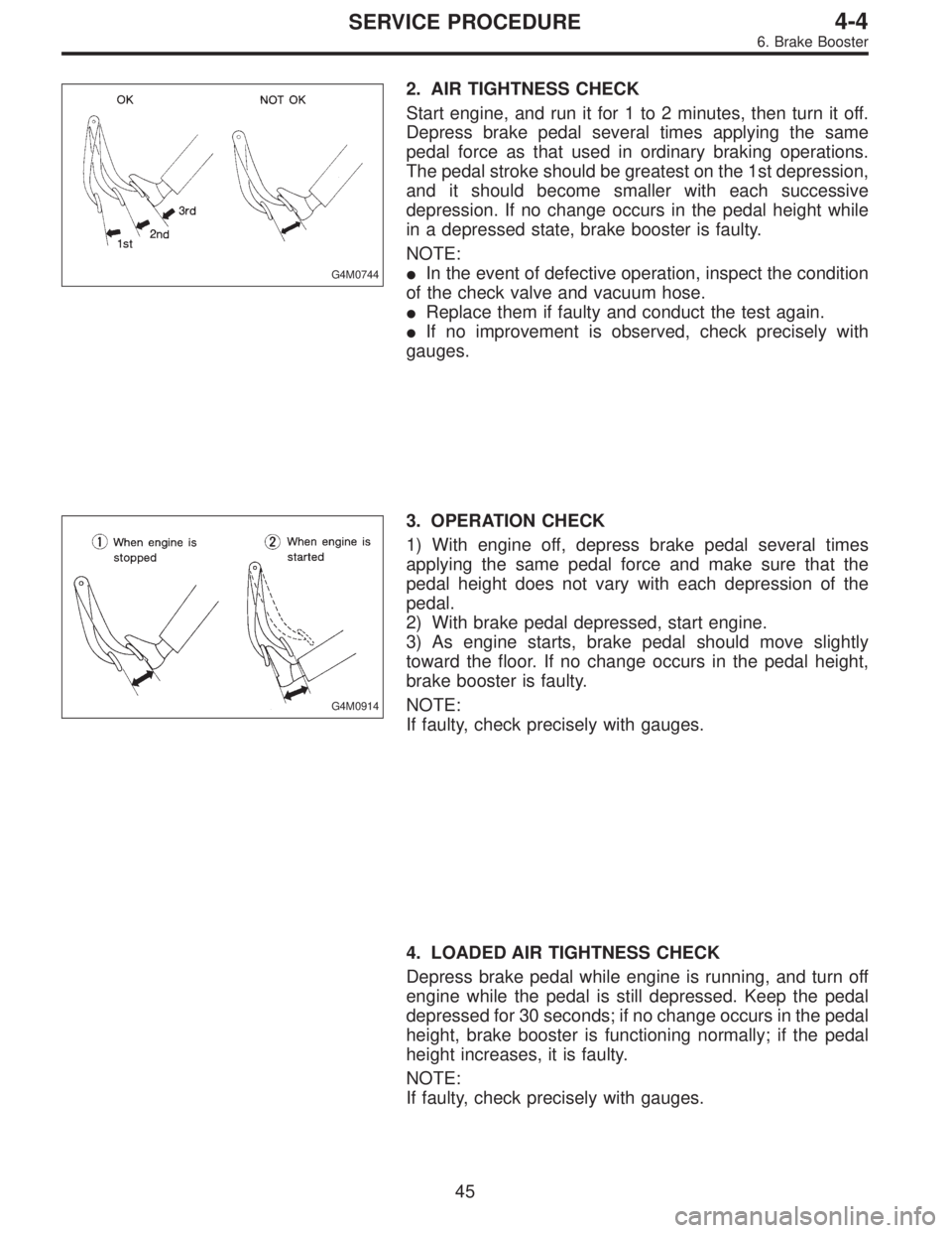
2. AIR TIGHTNESS CHECK
Start engine, and run it for 1 to 2 minutes, then turn it off.
Depress brake pedal several times applying the same
pedal force as that used in ordinary braking operations.
The pedal stroke should be greatest on the 1st depression,
and it should become smaller with each successive
depression. If no change occurs in the pedal height while
in a depressed state, brake booster is faulty.
NOTE:
�In the event of defective operation, inspect the condition
of the check valve and vacuum hose.
�Replace them if faulty and conduct the test again.
�If no improvement is observed, check precisely with
gauges.
G4M0914
3. OPERATION CHECK
1) With engine off, depress brake pedal several times
applying the same pedal force and make sure that the
pedal height does not vary with each depression of the
pedal.
2) With brake pedal depressed, start engine.
3) As engine starts, brake pedal should move slightly
toward the floor. If no change occurs in the pedal height,
brake booster is faulty.
NOTE:
If faulty, check precisely with gauges.
4. LOADED AIR TIGHTNESS CHECK
Depress brake pedal while engine is running, and turn off
engine while the pedal is still depressed. Keep the pedal
depressed for 30 seconds; if no change occurs in the pedal
height, brake booster is functioning normally; if the pedal
height increases, it is faulty.
NOTE:
If faulty, check precisely with gauges.
45
4-4SERVICE PROCEDURE
6. Brake Booster
Page 875 of 2248
4. O-ring Connections
1. GENERAL
The following points should be kept in mind when assem-
bling O-ring connections.
1) Avoid unnecessary handling and contact of O-rings with
your hands, since even clean fingers contain body acids,
which can contaminate the O-ring surface.
2) Do not handle O-rings with gloves, shop towels, etc.,
since lint particles may cling to the O-ring, possibly caus-
ing a leak upon assembly.
3) Always lubricate O-rings before assembly to allow the
O-ring to seat itself properly.
4) Be certain to use torque wrenches when tightening
O-ring fittings, because overtightening can not only dam-
age the O-ring, but it can distort the tube end as well.
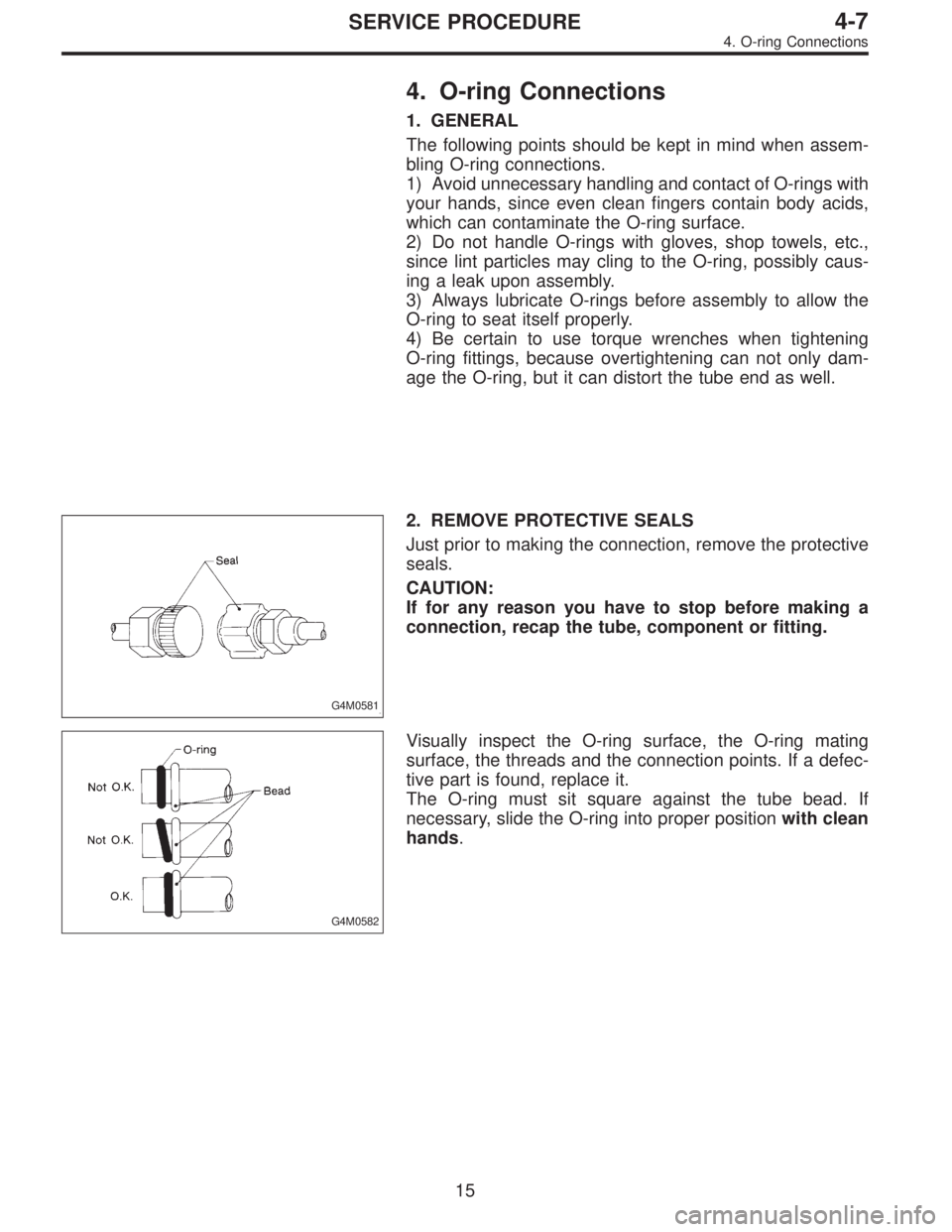
G4M0581
2. REMOVE PROTECTIVE SEALS
Just prior to making the connection, remove the protective
seals.
CAUTION:
If for any reason you have to stop before making a
connection, recap the tube, component or fitting.
G4M0582
Visually inspect the O-ring surface, the O-ring mating
surface, the threads and the connection points. If a defec-
tive part is found, replace it.
The O-ring must sit square against the tube bead. If
necessary, slide the O-ring into proper positionwith clean
hands.
15
4-7SERVICE PROCEDURE
4. O-ring Connections
Page 876 of 2248
G4M0583
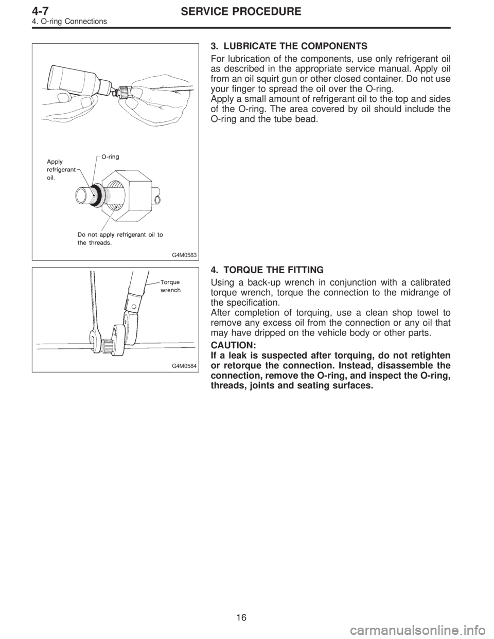
3. LUBRICATE THE COMPONENTS
For lubrication of the components, use only refrigerant oil
as described in the appropriate service manual. Apply oil
from an oil squirt gun or other closed container. Do not use
your finger to spread the oil over the O-ring.
Apply a small amount of refrigerant oil to the top and sides
of the O-ring. The area covered by oil should include the
O-ring and the tube bead.
G4M0584
4. TORQUE THE FITTING
Using a back-up wrench in conjunction with a calibrated
torque wrench, torque the connection to the midrange of
the specification.
After completion of torquing, use a clean shop towel to
remove any excess oil from the connection or any oil that
may have dripped on the vehicle body or other parts.
CAUTION:
If a leak is suspected after torquing, do not retighten
or retorque the connection. Instead, disassemble the
connection, remove the O-ring, and inspect the O-ring,
threads, joints and seating surfaces.
16
4-7SERVICE PROCEDURE
4. O-ring Connections