Page 883 of 2248
 The A/C system to be tested must have an adequate
refrigerant charge to begin with.
2) The are")
8. Leak Testing
The following points should be kept in mind when conduct-
ing a refrigerant leak test.
1) The A/C system to be tested must have an adequate
refrigerant charge to begin with.
2) The area where the leak test is conducted must be free
of wind and drafts, with still air being the ideal condition.
3) The atmosphere where the leak test is conducted must
be free of refrigerant contamination.
4) Operate the A/C system for approx. 10 minutes, then
turn the engine off an begin the leak test.
5) Refrigerant gas is heavier than air, therefore always
hold the probe below the connection being tested.
6) When checking for a leak along a length of hose or
tube, the leak detector probe must be moved slowly,
approx. 25 mm (1 in) per second making sure probe does
not come in contact with the component being tested.
7) When checking for a leak at a certain point, the leak
detector probe must be held at that point for at least 5
seconds.
G4M0609
1. CHECK THE SYSTEM PRESSURE
With gauges connected to the A/C system, operate the A/C
and confirm that the high side pressure is above 690 kPa
(7.03 kg/cm
2, 100 psi). If not, evacuate and charge the
system before leak checking (refer to evacuation and
charging sections).
2. CLEAN CONNECTIONS BEFORE TESTING
Before testing, use a clean shop towel to wipe off refriger-
ant oil, dirt, or foreign material from all of the connections
and components to be tested.
NOTE:
Since refrigerant oil absorbs refrigerant, excess oil on or
near a connection may falsely signal a leak.
B4M0089
3. CALIBRATE LEAK DETECTOR
Refer to the manufacturer’s instructions for the particular
type of detector used and calibrate the instrument.
CAUTION:
Always make sure that the probe tip filter is clean and
free of contamination.
23
4-7SERVICE PROCEDURE
8. Leak Testing
Page 963 of 2248
G5M0175
B: INSTALLATION
1) Installation is in the reverse order of removal.
2) Check for alignment of front fender with hood and front
door with front fender at all points. Adjust, if necessary.
B5M0287A
9. Mud Guard and Rear Arch
Protector
A: REMOVAL
SUPPLEMENTAL RESTRAINT SYSTEM“AIRBAG”
Airbag system wiring harness is routed near the mud
guard.
CAUTION:
�All Airbag system wiring harness and connectors
are colored yellow. Do not use electrical test equip-
ment on these circuits.
�Be careful not to damage Airbag system wiring har-
ness when servicing the mud guard.
B5M0288
1. MUD GUARD
1) Jack-up vehicle to remove tire.
2) Remove screws and clips. Move mud guard toward the
center of the body and remove mud guard.
46
5-1SERVICE PROCEDURE
8. Front Fender - 9. Mud Guard and Rear Arch Protector
Page 964 of 2248
G5M0175
B: INSTALLATION
1) Installation is in the reverse order of removal.
2) Check for alignment of front fender with hood and front
door with front fender at all points. Adjust, if necessary.
B5M0287A
9. Mud Guard and Rear Arch
Protector
A: REMOVAL
SUPPLEMENTAL RESTRAINT SYSTEM“AIRBAG”
Airbag system wiring harness is routed near the mud
guard.
CAUTION:
�All Airbag system wiring harness and connectors
are colored yellow. Do not use electrical test equip-
ment on these circuits.
�Be careful not to damage Airbag system wiring har-
ness when servicing the mud guard.
B5M0288
1. MUD GUARD
1) Jack-up vehicle to remove tire.
2) Remove screws and clips. Move mud guard toward the
center of the body and remove mud guard.
46
5-1SERVICE PROCEDURE
8. Front Fender - 9. Mud Guard and Rear Arch Protector
Page 999 of 2248
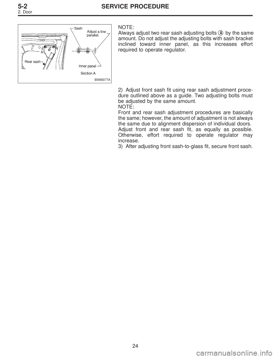
B5M0077A
NOTE:
Always adjust two rear sash adjusting bolts�
Aby the same
amount. Do not adjust the adjusting bolts with sash bracket
inclined toward inner panel, as this increases effort
required to operate regulator.
2) Adjust front sash fit using rear sash adjustment proce-
dure outlined above as a guide. Two adjusting bolts must
be adjusted by the same amount.
NOTE:
Front and rear sash adjustment procedures are basically
the same; however, the amount of adjustment is not always
the same due to alignment dispersion of individual doors.
Adjust front and rear sash fit, as equally as possible.
Otherwise, effort required to operate regulator may
increase.
3) After adjusting front sash-to-glass fit, secure front sash.
24
5-2SERVICE PROCEDURE
2. Door
Page 1133 of 2248
 When tester indicates 12 volts when its probe reaches
point“A”, a broken circuit occurs between point“A”and the
negative terminal. Slowly move tester probe toward the
negative termi")
G6M0137
4) When tester indicates 12 volts when its probe reaches
point“A”, a broken circuit occurs between point“A”and the
negative terminal. Slowly move tester probe toward the
negative terminal while contacting it on heat wire to locate
point where tester indication changes abruptly (0 volts).
This is the point where a broken circuit occurs.
When tester indicates 0 volts when its probe reaches point
“A”, a broken circuit occurs between point“A”and the posi-
tive terminal. Locate a point where tester indication
changes abruptly (12 volts) while slowly moving tester
probe toward the positive terminal.
G6M0138
C: REPAIR
1) Clean broken wire and its surrounding area.
2) Cut off slit on (used) thin film by 0.5 mm (0.020 in) width
and 10 mm (0.39 in) length.
3) Place the slit on glass along the broken wire, and
deposit conductive silver composition (DUPONT No. 4817)
on the broken portion.
4) Dry out the deposited portion.
5) Inspect the repaired wire for continuity.
B6M0120
13. Combination Meter
A: REMOVAL AND INSTALLATION
1. COMBINATION METER
1) Move steering wheel fully down.
2) Remove screws which secure meter visor.
3) Remove visor from instrument panel.
4) Disconnect connectors from meter visor.
B6M0121
5) Remove screws which secure combination meter, and
pull combination meter out.
6) Disconnect connectors from back of combination meter.
CAUTION:
When installing combination meter, be sure to connect
connectors to backside of combination meter.
33
6-2SERVICE PROCEDURE
12. Rear Window Defogger - 13. Combination Meter
Page 1134 of 2248
 When tester indicates 12 volts when its probe reaches
point“A”, a broken circuit occurs between point“A”and the
negative terminal. Slowly move tester probe toward the
negative termi")
G6M0137
4) When tester indicates 12 volts when its probe reaches
point“A”, a broken circuit occurs between point“A”and the
negative terminal. Slowly move tester probe toward the
negative terminal while contacting it on heat wire to locate
point where tester indication changes abruptly (0 volts).
This is the point where a broken circuit occurs.
When tester indicates 0 volts when its probe reaches point
“A”, a broken circuit occurs between point“A”and the posi-
tive terminal. Locate a point where tester indication
changes abruptly (12 volts) while slowly moving tester
probe toward the positive terminal.
G6M0138
C: REPAIR
1) Clean broken wire and its surrounding area.
2) Cut off slit on (used) thin film by 0.5 mm (0.020 in) width
and 10 mm (0.39 in) length.
3) Place the slit on glass along the broken wire, and
deposit conductive silver composition (DUPONT No. 4817)
on the broken portion.
4) Dry out the deposited portion.
5) Inspect the repaired wire for continuity.
B6M0120
13. Combination Meter
A: REMOVAL AND INSTALLATION
1. COMBINATION METER
1) Move steering wheel fully down.
2) Remove screws which secure meter visor.
3) Remove visor from instrument panel.
4) Disconnect connectors from meter visor.
B6M0121
5) Remove screws which secure combination meter, and
pull combination meter out.
6) Disconnect connectors from back of combination meter.
CAUTION:
When installing combination meter, be sure to connect
connectors to backside of combination meter.
33
6-2SERVICE PROCEDURE
12. Rear Window Defogger - 13. Combination Meter
Page 1264 of 2248
 After the display is gone, turn Subaru select monitor
switch and ignition switch to OFF.
NOTE:
When the ECM, battery terminals, etc. are disconnected
after memory is cleared, idling speed m")
G3M0151
6) After the display is gone, turn Subaru select monitor
switch and ignition switch to OFF.
NOTE:
When the ECM, battery terminals, etc. are disconnected
after memory is cleared, idling speed may increase. This is
not considered a problem because the ISC valve duty con-
trolled learning value has been cleared. To return the
engine to idling speed, idle for approximately 2 minutes
with air conditioner off.
2. OBD-II GENERAL SCAN TOOL
For clear memory procedures using the OBD-II general
scan tool, refer to the OBD-II General Scan Tool Instruction
Manual.
OBD0072A
E: INSPECTION MODE
1. PREPARATIONS FOR THE INSPECTION MODE
Raise the vehicle using a garage jack and place on safety
stands or drive the vehicle onto free rollers.
�FULL-TIME AWD MODELS
WARNING:
�Before raising the vehicle, ensure parking brakes
are applied.
�Do not use a pantograph jack in place of a safety
stand.
�Secure a rope or wire to the front and rear towing or
tie-down hooks to prevent the lateral runout of front
wheels.
�Do not abruptly depress/release clutch pedal or
accelerator pedal during works even when engine is
operating at low speeds since this may cause vehicle
to jump off free rollers.
�In order to prevent the vehicle from slipping due to
vibration, do not place any wooden blocks or similar
items between the safety stands and the vehicle.
58
2-7ON-BOARD DIAGNOSTICS II SYSTEM
3. Diagnosis System
Page 1265 of 2248

�Since the rear wheels will also roting, do not place
anything near them. Also, make sure that nobody goes
in front of the vehicle.
OBD0073A
�FWD MODELS
WARNING:
�Before raising the vehicle, ensure parking brakes
are applied.
�Do not use a pantograph jack in place of a safety
stand.
�If only the front wheels are raised or placed on a free
roller, apply parking brakes and lock the rear wheels.
�Secure a rope or wire to the front and rear towing or
tie-down hooks to prevent the lateral runout of front
wheels.
�Do not abruptly depress/release clutch pedal or
accelerator pedal during works even when engine is
operating at low speeds since this may cause vehicle
to jump off free rollers.
�In order to prevent the vehicle from slipping due to
vibration, do not place any wooden blocks or similar
items between the safety stands and the vehicle.
�Since the rear wheels will also roting, do not place
anything near them. Also, make sure that nobody goes
in front of the vehicle.
59
2-7ON-BOARD DIAGNOSTICS II SYSTEM
3. Diagnosis System
 Installation is in the reverse order of removal.
2) Check for alignment of front fender with hood and front
door with front fender at all points. Adjust, if necessary.
B5M02")
 Installation is in the reverse order of removal.
2) Check for alignment of front fender with hood and front
door with front fender at all points. Adjust, if necessary.
B5M02")