Page 340 of 2248
G3M0666
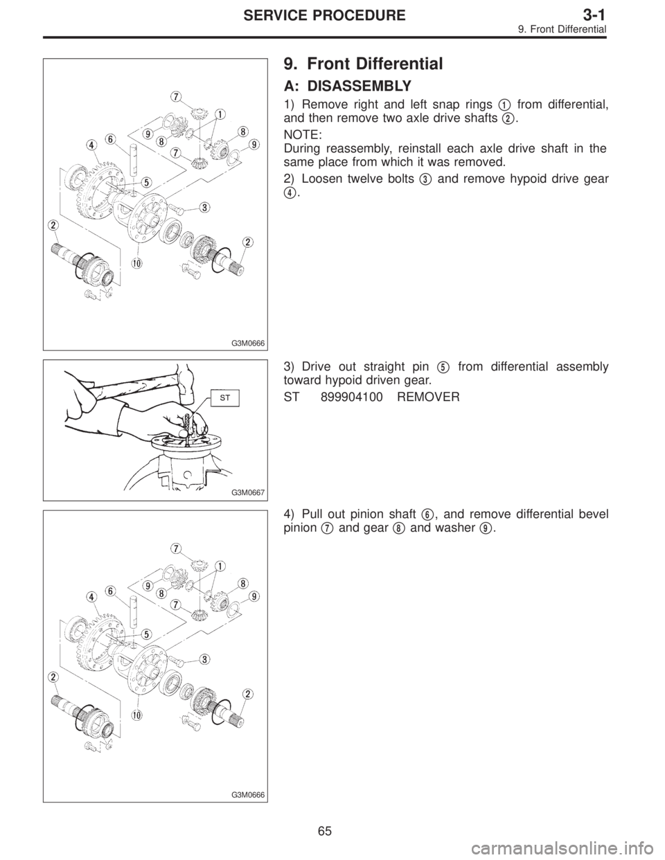
9. Front Differential
A: DISASSEMBLY
1) Remove right and left snap rings�1from differential,
and then remove two axle drive shafts�
2.
NOTE:
During reassembly, reinstall each axle drive shaft in the
same place from which it was removed.
2) Loosen twelve bolts�
3and remove hypoid drive gear
�
4.
G3M0667
3) Drive out straight pin�5from differential assembly
toward hypoid driven gear.
ST 899904100 REMOVER
G3M0666
4) Pull out pinion shaft�6, and remove differential bevel
pinion�
7and gear�8and washer�9.
65
3-1SERVICE PROCEDURE
9. Front Differential
Page 341 of 2248
G3M0668
5) Remove roller bearing using ST.
ST 399527700 PULLER SET
B3M0099A
B: ASSEMBLY
1) Install bevel gear and bevel pinion together with
washers, and insert pinion shaft�
1.
NOTE:
Face the chamfered side of washer toward gear.
G3M0670
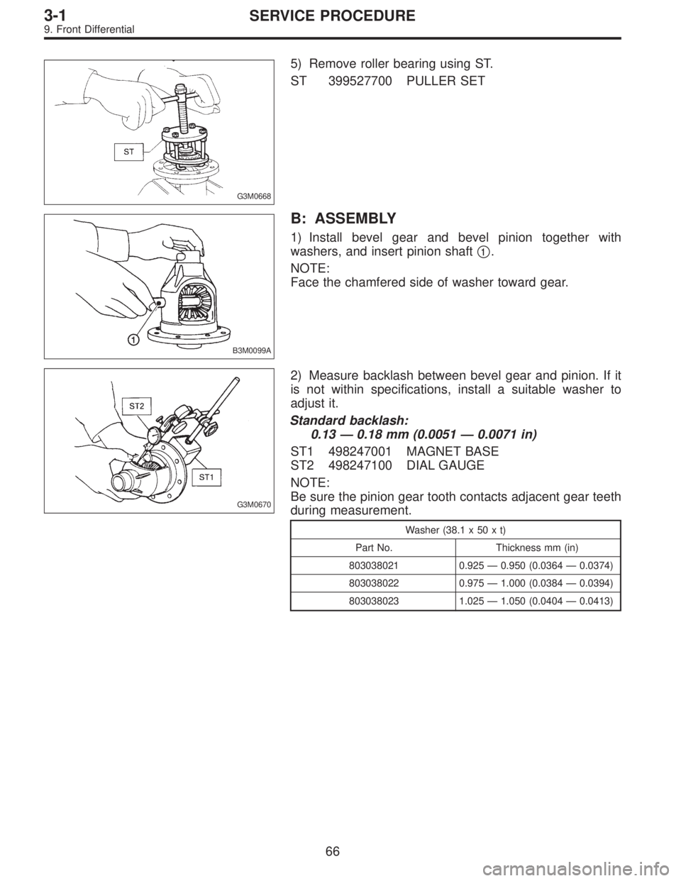
2) Measure backlash between bevel gear and pinion. If it
is not within specifications, install a suitable washer to
adjust it.
Standard backlash:
0.13—0.18 mm (0.0051—0.0071 in)
ST1 498247001 MAGNET BASE
ST2 498247100 DIAL GAUGE
NOTE:
Be sure the pinion gear tooth contacts adjacent gear teeth
during measurement.
Washer (38.1 x 50 x t)
Part No. Thickness mm (in)
803038021 0.925—0.950 (0.0364—0.0374)
803038022 0.975—1.000 (0.0384—0.0394)
803038023 1.025—1.050 (0.0404—0.0413)
66
3-1SERVICE PROCEDURE
9. Front Differential
Page 407 of 2248
 Apply red lead evenly to the surfaces of three or
four teeth of the crown gear. Rotate the drive pinion in
the forward and reverse directions several times. Then
remove the oil pump housing, and c")
(8) Apply red lead evenly to the surfaces of three or
four teeth of the crown gear. Rotate the drive pinion in
the forward and reverse directions several times. Then
remove the oil pump housing, and check the tooth con-
tact pattern.
If tooth contact is improper, readjust the backlash or
shim thickness.
Checking item Contact pattern Corrective action
Tooth contact
Tooth contact pattern is slightly shifted
toward to under no-load rotation.
[When loaded, contact pattern moves
toward heel.]
B3M0317A
Face contact
Backlash is too large.This may cause noise and chipping at
tooth ends.
B3M0319
Increase thickness of drive pinion height
adjusting shim in order to bring drive pinion
close to crown gear.
B3M0323
Flank contact
Backlash is too small.This may cause noise and stepped wear
on surfaces.
B3M0320
Reduce thickness of drive pinion height
adjusting shim in order to move drive pin-
ion away from crown gear.
B3M0324
Toe contact
(Inside end contact)
Contact areas is small.This may cause chipping at toe ends.
B3M0321
Adjust as for flank contact.
B3M0324
Heel contact
(Outside end contact)
Contact area is small.This may cause chipping at heel ends.
B3M0322
Adjust as for face contact.
B3M0323
: Adjusting direction of drive pinion
: Adjusting direction of crown gear
63
3-2SERVICE PROCEDURE
4. Overall Transmission
Page 512 of 2248

TOOTH CONTACT PATTERN
Condition Contact pattern Adjustment
Correct tooth contact
Tooth contact pattern slightly shifted
towards toe under no load rotation.
(When loaded, contact pattern moves
toward heel.)
B3M0317A
Face contact
Backlash is too large.This may cause noise and chipping at
tooth ends.
B3M0319
Increase thickness of drive pinion height
adjusting shim in order to bring drive
pinion closer to crown gear center.
B3M0323
Flank contact
Backlash is too small.This may cause noise and stepped wear
on surfaces.
B3M0320
Reduce thickness of drive pinion height
adjusting shim in order to move drive
pinion away from crown gear.
B3M0324
Toe contact
Contact area is small.This may cause chipping at toe ends.
B3M0321
Adjust as for flank contact.
B3M0324
Heel contact
Contact area is small.This may cause chipping at heel ends.
B3M0322
Adjust as for face contact.
B3M0323
: Adjusting direction of drive pinion
: Adjusting direction of crown gear
36
3-4SERVICE PROCEDURE
2. Rear Differential
Page 647 of 2248
 Remove flare nuts from control valve of gearbox
assembly, and disconnect upper and lower hoses B and A.
CAUTION:
�Always disconnect hoses B and A in that order.
�Be careful not to damage the hoses")
9) Remove flare nuts from control valve of gearbox
assembly, and disconnect upper and lower hoses B and A.
CAUTION:
�Always disconnect hoses B and A in that order.
�Be careful not to damage the hoses during removal.
10) Remove bolts securing gearbox to crossmember, and
detach gearbox.
G4M0788
B: DISASSEMBLY
1) Disconnect four pipes from gearbox.
2) Secure gearbox removed from vehicle in vice using ST.
ST 926200000 STAND
CAUTION:
Secure the gearbox assembly in a vice using the ST as
shown. Do not attempt to secure it without this ST.
G4M0789
3) Pry off clip from outer end of boot, and slide boot toward
tie-rod end.
G4M0790
4) Using ST, remove lock wire from inner end of boot, and
remove boot.
ST 927590000 WRENCH
G4M0791
5) Extend rack approximately 40 mm (1.57 in) out. Unlock
lock wire at lock washer on each side of tie-rod end using
a standard screwdriver.
CAUTION:
Be careful not to scratch rack surface as oil leaks may
result.
31
4-3SERVICE PROCEDURE
4. Steering Gearbox (Power Steering System) [RHD model]
Page 657 of 2248

2. OIL LEAK CHECK PROCEDURE AND
REPLACEMENT PARTS
NOTE:
Parts requiring replacement are described in the smallest
unit of spare parts including damaged parts and spare
parts damaged. In actual disassembly work, accidental
damage as well as inevitable damage to some related
parts must be taken into account, and spare parts for them
must also be prepared. However, it is essential to pinpoint
the cause of trouble, and limit the number of replacement
parts as much as possible.
1) Leakage from“a”
The oil seal is damaged. Replace valve assembly with a
new one.
2) Leakage from“b”
The torsion bar O-ring is damaged. Replace valve assem-
bly with a new one.
3) Leakage from“c”
The oil seal is damaged. Replace valve assembly with a
new one.
4) Leakage from“d”
The pipe is damaged. Replace the faulty pipe or O-ring.
5) If leak is other than a, b, c, or d, and if oil is leaking from
the gearbox, move the right and left boots toward tie-rod
end side, respectively, with the gearbox mounted to the
vehicle, and remove oil from the surrounding portions.
Then, turn the steering wheel from lock to lock 30 to 40
times with the engine running, then make comparison of
the leaked portion immediately after and several hours
after this operation.
6) Leakage from“e”
The cylinder seal is damaged. Replace rack bush with a
new one.
7) Leakage from“f”
There are two possible causes. Take following step first.
Remove the pipe assembly B from the valve housing, and
close the circuit with ST.
ST 926420000 PLUG
Turn the steering wheel from lock to lock 30 to 40 times
with the engine running, then make comparison of the
leaked portion between immediately after and several
hours after this operation.
CAUTION:
�If leakage from“f”is noted again:
The oil seal of pinion and valve assembly is damaged.
Replace pinion and valve assembly with a new one. Or
replace the oil seal and the parts that are damaged
during disassembly with new ones.
�If oil stops leaking from“f”:
The oil seal of rack housing is damaged.
Replace the oil seal and the parts that are damaged
during disassembly with new ones.
41
4-3SERVICE PROCEDURE
5. Control Valve (Power Steering Gearbox) [LHD model]
Page 664 of 2248
G4M0158
2. VALVE ASSEMBLY
1) Apply genuine grease to pinion gear and bearing of
valve assembly.
B4M0135
2) Install packing on valve assembly. Insert valve assem-
bly into place while facing rack teeth toward pinion.
CAUTION:
Be sure to use a new packing.
NOTE:
Do not allow packing to be caught when installing valve
assembly.
3) Tighten bolts alternately to secure valve assembly.
Tightening torque:
25±5 N⋅m (2.5±0.5 kg-m, 18.1±3.6 ft-lb)
CAUTION:
Be sure to alternately tighten bolts.
48
4-3SERVICE PROCEDURE
5. Control Valve (Power Steering Gearbox) [LHD model]
Page 666 of 2248

2. OIL LEAK CHECK PROCEDURE AND
REPLACEMENT PARTS
NOTE:
Parts requiring replacement are described in the smallest
unit of spare parts including damaged parts and spare
parts damaged. In actual disassembly work, accidental
damage as well as inevitable damage to some related
parts must be taken into account, and spare parts for them
must also be prepared. However, it is essential to pinpoint
the cause of trouble, and limit the number of replacement
parts as much as possible.
1) Leakage from“a”
The oil seal is damaged. Replace valve assembly with a
new one.
2) Leakage from“b”
The torsion bar O-ring is damaged. Replace valve assem-
bly with a new one.
3) Leakage from“c”
The oil seal is damaged. Replace valve assembly with a
new one.
4) Leakage from“d”
The pipe is damaged. Replace the faulty pipe or O-ring.
5) If leak is other than a, b, c, or d, and if oil is leaking from
the gearbox, move the right and left boots toward tie-rod
end side, respectively, with the gearbox mounted to the
vehicle, and remove oil from the surrounding portions.
Then, turn the steering wheel from lock to lock 30 to 40
times with the engine running, then make comparison of
the leaked portion immediately after and several hours
after this operation.
6) Leakage from“e”
There are two possible causes. Take following step first.
Remove the pipe assembly B from the valve housing, and
close the circuit with ST.
ST 926420000 PLUG
Turn the steering wheel from lock to lock 30 to 40 times
with the engine running, then make comparison of the
leaked portion between immediately after and several
hours after this operation.
CAUTION:
�If leakage from“e”is noted again:
The oil seal of pinion and valve assembly is damaged.
Replace pinion and valve assembly with a new one. Or
replace the oil seal and the parts that are damaged
during disassembly with new ones.
�If oil stops leaking from“e”:
The oil seal of rack housing is damaged.
Replace the oil seal and the parts that are damaged
during disassembly with new ones.
50
4-3SERVICE PROCEDURE
6. Control Valve (Power Steering Gearbox) [RHD model]
 Apply genuine grease to pinion gear and bearing of
valve assembly.
B4M0135
2) Install packing on valve assembly. Insert valve assem-
bly into place while facing rack teeth")