Page 48 of 2248
B: DISASSEMBLY
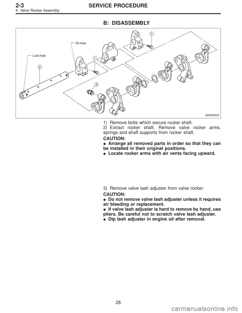
B2M0383A
1) Remove bolts which secure rocker shaft.
2) Extract rocker shaft. Remove valve rocker arms,
springs and shaft supports from rocker shaft.
CAUTION:
�Arrange all removed parts in order so that they can
be installed in their original positions.
�Locate rocker arms with air vents facing upward.
3) Remove valve lash adjuster from valve rocker.
CAUTION:
�Do not remove valve lash adjuster unless it requires
air bleeding or replacement.
�If valve lash adjuster is hard to remove by hand, use
pliers. Be careful not to scratch valve lash adjuster.
�Dip lash adjuster in engine oil after removal.
28
2-3SERVICE PROCEDURE
4. Valve Rocker Assembly
Page 51 of 2248
D: ASSEMBLY
B2M0383B
Tightening torque: N⋅m (kg-m, ft-lb)
T: 5±1 (0.5±0.1, 3.6±0.7)
1) After bleeding air from hydraulic lash adjuster, position
hydraulic lash adjuster in valve rocker arm while dipping in
engine oil.
CAUTION:
�Fill rocker arm oil reservoir chamber with engine oil.
�Install a new hydraulic lash adjuster O-ring, being
careful not to scratch it.
�Do not attempt to rotate hydraulic lash adjuster dur-
ing installation.
2) Arrange valve rocker arms, springs and shaft supports
in assembly order and insert valve rocker shaft. Ensure
that cutout portion of rocker shaft faces oil holes�
Ain shaft
supports.
CAUTION:
Valve rocker arms, rocker shaft and shaft supports
have identification marks. Ensure parts with same
markings are properly assembled.
3) Install valve rocker shaft securing bolts while aligning
shaft“lock”holes�
Bwith bolts.
31
2-3SERVICE PROCEDURE
4. Valve Rocker Assembly
Page 73 of 2248
G2M0163
7) Removal of oil pan
(1) Turn cylinder block with #2 and #4 piston sides
facing upward.
(2) Remove bolts which secure oil pan to cylinder
block.
(3) Insert a oil pan cutter blade between cylinder block-
to-oil pan clearance and remove oil pan.
CAUTION:
Do not use a screwdriver or similar tool in place of oil-
pan cutter.
8) Remove oil strainer stay.
9) Remove oil strainer.
10) Remove baffle plate.
11) Remove oil filter.
B: DISASSEMBLY
1. PISTON PIN AND CYLINDER BLOCK
CONNECTING BOLT
G2M0164
52
2-3SERVICE PROCEDURE
7. Cylinder Block
Page 104 of 2248
 Remove oil pump by using flat-bladed screwdriver.
CAUTION:
Be careful not to scratch mating surfaces of cylinder
block and oil pump.
B2M0315A
B: DISASSEMBLY
Remove screws which secure oil p")
G2M0071
7) Remove oil pump by using flat-bladed screwdriver.
CAUTION:
Be careful not to scratch mating surfaces of cylinder
block and oil pump.
B2M0315A
B: DISASSEMBLY
Remove screws which secure oil pump cover and disas-
semble oil pump.
Inscribe alignment marks on inner and outer rotors so that
they can be replaced in their original positions during reas-
sembly.
CAUTION:
Before removing relief valve, loosen plug when remov-
ing oil pump from cylinder block.
�
1Oil seal
�
2Pump case
�
3Inner rotor
�
4Outer rotor
�
5Pump cover
�
6Relief valve
�
7Relief spring
�
8Plug
�
9Washer
�
10O-ring
B2M0316A
C: INSPECTION
1. TIP CLEARANCE
Measure the tip clearance of rotors. If the clearance
exceeds the limit, replace rotors as a matched set.
Tip clearance:
Standard
0.04—0.14 mm (0.0016—0.0055 in)
Limit
0.18 mm (0.0071 in)
B2M0317A
2. CASE CLEARANCE
Measure the clearance between the outer rotor and the
cylinder block rotor housing. If the clearance exceeds the
limit, replace the rotor.
Case clearance:
Standard
0.10—0.175 mm (0.0039—0.0069 in)
Limit
0.20 mm (0.0079 in)
5
2-4SERVICE PROCEDURE
1. Oil Pump
Page 209 of 2248
G2M0373
9. Roll Over Valve
A: REMOVAL
1) Lift up the vehicle.
2) Remove roll over valve with bracket.
3) Disconnect hoses from roll over valve, and remove it
from bracket.
G2M0374
B: INSPECTION
1) Connect hoses to roll over valve as shown in Figure.
2) While blowing through open end of hose, tilt valve at
least 90° left and right from normal position.
3) Ensure that there is no air flow when hose is tilted
greater than 90°.
G2M0373
C: INSTALLATION
Installation is in the reverse order of removal.
CAUTION:
�Do not install top side of valve down.
�Before installing bracket on body, securely fit con-
cave part of bracket to hole in body.
G6M0095
10. Fuel Sub Meter Unit (AWD model
only)
A: REMOVAL AND INSTALLATION
1) Disconnect battery ground cable.
G2M0863
2) Remove rear seat.
3) Remove service hole cover.
20
2-8SERVICE PROCEDURE
9. Roll Over Valve - 10. Fuel Sub Meter Unit (Turbo model only)
Page 210 of 2248
G2M0373
9. Roll Over Valve
A: REMOVAL
1) Lift up the vehicle.
2) Remove roll over valve with bracket.
3) Disconnect hoses from roll over valve, and remove it
from bracket.
G2M0374
B: INSPECTION
1) Connect hoses to roll over valve as shown in Figure.
2) While blowing through open end of hose, tilt valve at
least 90° left and right from normal position.
3) Ensure that there is no air flow when hose is tilted
greater than 90°.
G2M0373
C: INSTALLATION
Installation is in the reverse order of removal.
CAUTION:
�Do not install top side of valve down.
�Before installing bracket on body, securely fit con-
cave part of bracket to hole in body.
G6M0095
10. Fuel Sub Meter Unit (AWD model
only)
A: REMOVAL AND INSTALLATION
1) Disconnect battery ground cable.
G2M0863
2) Remove rear seat.
3) Remove service hole cover.
20
2-8SERVICE PROCEDURE
9. Roll Over Valve - 10. Fuel Sub Meter Unit (Turbo model only)
Page 213 of 2248
 Fuel pump will not operate.
�Defective terminal contact.Inspect connections, especially groun")
1. Fuel System
Trouble and possible cause Corrective action
1. Insufficient fuel supply to the injector
1) Fuel pump will not operate.
�Defective terminal contact.Inspect connections, especially ground, and tighten
securely.
�Trouble in electromagnetic or electronic circuit parts. Replace fuel pump.
2) Lowering of fuel pump function. Replace fuel pump.
3) Clogged dust or water in the fuel filter. Replace fuel filter, clean or replace fuel tank.
4) Clogged or bent fuel pipe or hose. Clean, correct or replace fuel pipe or hose.
5) Air is mixed in the fuel system. Inspect or retighten each connection part.
6) Clogged or bent breather tube or pipe. Clean, correct or replace air breather tube or pipe.
7) Damaged diaphragm of pressure regulator. Replace.
2. Leakage or blow out fuel
1) Loosened joints of the fuel pipe. Retightening.
2) Cracked fuel pipe, hose and fuel tank. Replace.
3) Defective welding part on the fuel tank. Replace.
4) Defective drain packing of the fuel tank. Replace.
5) Clogged or bent air breather tube or air vent tube. Clean, correct or replace air breather tube or air vent tube.
3. Gasoline smell inside of compartment
1)Loose joints at air breather tube, air vent tube and fuel filler
pipe.Retightening.
2) Defective packing air tightness on the fuel saucer. Correct or replace packing.
3) Cracked fuel separator. Replace separator.
4. Defective fuel meter indicator
1) Defective operation of fuel meter unit. Replace.
2) Defective operation of fuel meter. Replace.
5. Noise
1) Large operation noise or vibration of fuel pump. Replace.
NOTE:
When the vehicle is left unattended for an extended period of time, water may accumulate in the fuel
tank.
�To prevent water condensation:
1) Top off the fuel tank or drain the fuel completely.
2) Drain water condensation from the fuel filter.
�Refilling the fuel tank:
Refill the fuel tank while there is still some fuel left in the tank.
�Protecting the fuel system against freezing and water condensation:
1) Cold areas
In snow-covered areas, mountainous areas, skiing areas, etc. where ambient temperatures drop
below 0°C (32°F) throughout the winter season, use an anti-freeze solution in the cooling system.
Refueling will also complement the effect of anti-freeze solution each time the fuel level drops to about
one-half. After the winter season, drain water which may have accumulated in the fuel filter and fuel
tank in the manner same as that described under affected areas as below.
2) Affected areas
When water condensation is notched in the fuel filter, drain water from both the fuel filter and fuel tank
or use a water removing agent (or anti-freeze solution) in the fuel tank.
�Observe the instructions, notes, etc., indicated on the label affixed to the anti-freeze solution (water
removing agent) container before use.
22
2-8DIAGNOSTICS
1. Fuel System
Page 223 of 2248
 Check the routing of clutch cable for smoothness.
2) Excessive tightnes")
1. General
A: PRECAUTION
When servicing clutch system, pay attention to the follow-
ing items.
1. MECHANICAL APPLICATION TYPE
1) Check the routing of clutch cable for smoothness.
2) Excessive tightness or looseness of clutch cable have
a bad influence upon the cable durability.
3) Apply grease sufficiently to the connecting portion of
clutch pedal.
4) Apply grease sufficiently to the release lever portion.
5) Position clutch cable through the center of toe board
hole and route it smoothly. Adjustment is done by moving
the outer cable.
6) Make sure not to let the clutch chatter when starting
forward or rearward. If clutch chattering occurs, readjust so
that the bend of clutch outer cable becomes flatter.
G2M0234
2. On-Car Service
1. MECHANICAL APPLICATION TYPE
1) Remove release lever return spring from lever (Models
without hill holder only).
2) Adjust spherical nut so that the play is within the speci-
fied value at the lever end (center of spherical nut).
CAUTION:
Take care not to twist the cable during adjustment
Play: 3 — 4 mm (0.12 — 0.16 in)
Full stroke: 24 — 26 mm (0.94 — 1.02 in)
G2M0235
3) Upon completion of adjustment, securely lock spherical
nut with lock nut.
Install return spring on lever (Models without hill holder
only).
NOTE:
Hook the long hook side of the return spring with the lever
(Models without hill holder only).
4
2-10SERVICE PROCEDURE
1. General - 2. On-Car Service

T: 5±1 (0.5±0.1, 3.6±0.7)
1) After bleeding air from hydraulic lash adjuster, position
hydraulic lash adjuster in valve rocker arm while")
 Removal of oil pan
(1) Turn cylinder block with #2 and #4 piston sides
facing upward.
(2) Remove bolts which secure oil pan to cylinder
block.
(3) Insert a oil pan cutter blade between cyli")
 Lift up the vehicle.
2) Remove roll over valve with bracket.
3) Disconnect hoses from roll over valve, and remove it
from bracket.
G2M0374
B: INSPECTION
1) Con")
 Lift up the vehicle.
2) Remove roll over valve with bracket.
3) Disconnect hoses from roll over valve, and remove it
from bracket.
G2M0374
B: INSPECTION
1) Con")