Page 101 of 2248

1. Lubrication System
A: SPECIFICATIONS
Lubrication methodForced lubrication
Oil pumpPump typeTrochoid type
Number of teethInner rotor 9
Outer rotor 10
Outer rotor diameter x thickness 78x9mm(3.07 x 0.35 in)
Tip clearance between inner and outer rotorSTANDARD 0.04 — 0.14 mm (0.0016 — 0.0055 in)
LIMIT 0.18 mm (0.0071 in)
Side clearance between inner rotor and pump
caseSTANDARD 0.02 — 0.07 mm (0.0008 — 0.0028 in)
LIMIT 0.15 mm (0.0059 in)
Case clearance between outer rotor and pump
caseSTANDARD 0.10 — 0.175 mm (0.0039 — 0.0069 in)
LIMIT 0.20 mm (0.0079 in)
Capacity at
80°C (176°F)700 rpm Discharge- pressure 98 kPa (1.0 kg/cm
2, 14 psi) or more
- quantity 4.2�(4.4 US qt, 3.7 Imp qt)/min.
5,000 rpm Discharge- pressure 294 kPa (3.0 kg/cm
2, 43 psi) or more
- quantity 42.0�(11.10 US gal, 9.24 Imp gal)/min.
Relief valve operation pressure 490 kPa (5.0 kg/cm
2, 71 psi)
Oil filterTypeFull-flow filter type
Filtration area 1,000 cm
2(155 sq in)
By-pass valve opening pressure 157 kPa (1.6 kg/cm
2, 23 psi)
Outer diameter x width 80 x 70 mm (3.15 x 2.76 in)
Oil filter to engine thread size M 20 x 1.5
Relief valve (on rocker shaft) operation pressure 69 kPa (0.7kg/cm
2, 10 psi)
Oil pressure
switchTypeImmersed contact point type
Working voltage — wattage 12 V — 3.4 W or less
Warning light activation pressure 14.7 kPa (0.15 kg/cm
2, 2.1 psi)
Proof pressure More than 981 kPa (10 kg/cm
2, 142 psi)
Oil pan capacity4.0�(4.2 US qt, 3.5 Imp qt)
2
2-4SPECIFICATIONS AND SERVICE DATA
1. Lubrication System
Page 945 of 2248
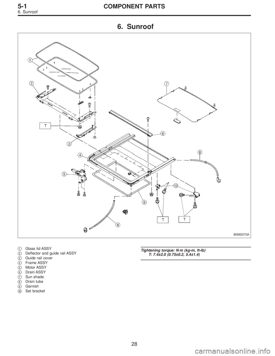
6. Sunroof
B5M0370A
�1Glass lid ASSY
�
2Deflector and guide rail ASSY
�
3Guide rail cover
�
4Frame ASSY
�
5Motor ASSY
�
6Drain ASSY
�
7Sun shade
�
8Drain tube
�
9Garnish
�
10Set bracket
Tightening torque: N⋅m (kg-m, ft-lb)
T: 7.4±2.0 (0.75±0.2, 5.4±1.4)
28
5-1COMPONENT PARTS
6. Sunroof
Page 971 of 2248
![SUBARU LEGACY 1995 Service Repair Manual B5M0304
15. Roof Rack (Wagon only, if
equipped)
A: REMOVAL
1) Remove roof trim, rear quarter trim, pillar trim, etc.
<Ref. to 5-3 [W5A0].>
2) Remove flange bolts.
3) Remove flange nuts.
4) Remove roof](/manual-img/17/57432/w960_57432-970.png "SUBARU LEGACY 1995 Service Repair Manual B5M0304
15. Roof Rack (Wagon only, if
equipped)
A: REMOVAL
1) Remove roof trim, rear quarter trim, pillar trim, etc.
<Ref. to 5-3 [W5A0].>
2) Remove flange bolts.
3) Remove flange nuts.
4) Remove roof")
B5M0304
15. Roof Rack (Wagon only, if
equipped)
A: REMOVAL
1) Remove roof trim, rear quarter trim, pillar trim, etc.
2) Remove flange bolts.
3) Remove flange nuts.
4) Remove roof rail.
B: INSTALLATION
Installation is in the reverse order of removal.
CAUTION:
To prevent deformation, be sure to install roof rail in
steps 4), 3), 2) and 1), in that order.
B5M0307A
16. Sunroof
A: REMOVAL
1. GLASS LID ASSEMBLY
1) Completely open sun shade. (Push it back far.)
2) Remove a clip and detach guide rail cover.
3) Remove six nuts from the left and right lid bracket.
4) Working inside, slightly raise glass lid assembly until it
is disengaged from lid bracket.
5) Hold both ends of glass lid assembly and remove it at
an angle.
B5M0308B
2. SUNROOF MOTOR AND RELAY
1) Remove center pillar trim upper.
2) Remove front pillar trim upper.
3) Remove assist grip on left side.
4) Remove sunvisor with hook.
5) Remove sunroof switch.
6) Remove rearview mirror.
7) While rolling up roof trim, disconnect harness clips and
connector.
8) While rolling up roof trim, remove spot lamp bracket and
sunroof motor.
51
5-1SERVICE PROCEDURE
15. Roof Rack (Wagon only, if equipped) - 16. Sunroof
Page 972 of 2248
![SUBARU LEGACY 1995 Service Repair Manual B5M0304
15. Roof Rack (Wagon only, if
equipped)
A: REMOVAL
1) Remove roof trim, rear quarter trim, pillar trim, etc.
<Ref. to 5-3 [W5A0].>
2) Remove flange bolts.
3) Remove flange nuts.
4) Remove roof](/manual-img/17/57432/w960_57432-971.png "SUBARU LEGACY 1995 Service Repair Manual B5M0304
15. Roof Rack (Wagon only, if
equipped)
A: REMOVAL
1) Remove roof trim, rear quarter trim, pillar trim, etc.
<Ref. to 5-3 [W5A0].>
2) Remove flange bolts.
3) Remove flange nuts.
4) Remove roof")
B5M0304
15. Roof Rack (Wagon only, if
equipped)
A: REMOVAL
1) Remove roof trim, rear quarter trim, pillar trim, etc.
2) Remove flange bolts.
3) Remove flange nuts.
4) Remove roof rail.
B: INSTALLATION
Installation is in the reverse order of removal.
CAUTION:
To prevent deformation, be sure to install roof rail in
steps 4), 3), 2) and 1), in that order.
B5M0307A
16. Sunroof
A: REMOVAL
1. GLASS LID ASSEMBLY
1) Completely open sun shade. (Push it back far.)
2) Remove a clip and detach guide rail cover.
3) Remove six nuts from the left and right lid bracket.
4) Working inside, slightly raise glass lid assembly until it
is disengaged from lid bracket.
5) Hold both ends of glass lid assembly and remove it at
an angle.
B5M0308B
2. SUNROOF MOTOR AND RELAY
1) Remove center pillar trim upper.
2) Remove front pillar trim upper.
3) Remove assist grip on left side.
4) Remove sunvisor with hook.
5) Remove sunroof switch.
6) Remove rearview mirror.
7) While rolling up roof trim, disconnect harness clips and
connector.
8) While rolling up roof trim, remove spot lamp bracket and
sunroof motor.
51
5-1SERVICE PROCEDURE
15. Roof Rack (Wagon only, if equipped) - 16. Sunroof
Page 973 of 2248
B5M0310A
3. SUNROOF FRAME
1) Remove sunroof switch, center and rear room lamps.
2) Remove roof trim, rear quarter trim, pillar trim, etc.
3) Remove glass lid assembly.
4) Remove two harness support clips.
G5M0205
5) Disconnect harness clips and connector of sunroof
motor.
6) Disconnect front and rear drain tubes.
CAUTION:
When installing drain tube, insert it securely into drain
pipe.
Length A:
15 mm (0.59 in) or more
B5M0312
7) Remove eight nuts.
B5M0382A
8) Remove set bracket mounting bolts.
9) Remove sunroof frame.
52
5-1SERVICE PROCEDURE
16. Sunroof
Page 974 of 2248
B: INSTALLATION
Installation is in the reverse order of removal.
B5M0314B
B5M0315B
C: ADJUSTMENTS
1. ALIGNMENT OF HEIGHT BETWEEN GLASS LID
ASSEMBLY AND ROOF PANEL
1) Remove guide rail cover.
2) Loosen nuts and adjust height by adding (Max: two
pieces) and extracting (Max: one piece) shim(s) (Standard:
one piece) between glass lid assembly and lid bracket.
Difference in height between glass lid assembly and
roof panel:
0±0.5 mm (0±0.020 in)
B5M0316A
2. ALIGNMENT OF GLASS LID ASSEMBLY WITH
ROOF PANEL
1) Remove guide rail cover.
2) Loosen nuts and move glass lid assembly to either side
to adjust front, rear, right, and left side partitions.
Partition clearance:
7.0±0.5 mm (0.276±0.020 in)
53
5-1SERVICE PROCEDURE
16. Sunroof
Page 975 of 2248
B5M0317
3. CHECKING FOR MOVEMENT OF GLASS LID
ASSEMBLY ITSELF
1) Before installing sunroof motor, check glass lid assem-
bly for movement.
2) Place a cloth on glass lid assembly and sun shade, and
attach a spring scale to glass lid assembly edge using the
cloth.
3) Pull spring scale to measure force required to move
glass lid assembly.
Force required to move glass lid assembly and sun
shade trim:
Less than 196 N (20 kg, 44 lb)
Considerable effort is required to start glass lid assembly
moving, so take scale reading while glass lid assembly is
moving smoothly.
4) If force required exceeds specifications, check the fol-
lowing points:
�Glass lid assembly, sun shade and deflector and guide
rail assembly for improper installation
�Cable for seizure
54
5-1SERVICE PROCEDURE
16. Sunroof
Page 976 of 2248

1. Sunroof
Entry of water into compartment�
1Check roof panel and glass lid assembly for improper or poor
sealing.
�
2Check drain tube for clogging.
�
3Check sunroof frame seal and body for improper fit.
Booming noise�
1Check glass lid assembly and roof panel for improper clear-
ance.
�
2Check sun shade and roof trim for improper clearance.
Abnormal motor noise�
1Check motor for looseness.
�
2Check gears and bearings for wear.
�
3Check cable for wear.
�
4Check cable pipe for deformities.
Failure of sunroof to operate
(Motor operates properly.)�
1Check guide rail for foreign particles.
�
2Check guide rail for improper installation.
�
3Check parts for mutual interference.
�
4Check cable slider for improper clinching.
�
5Check cable for improper installation.
�
6Check clutch adjustment nut for improper tightness.
Motor does not rotate or rotates improperly.
(Use sunroof wrench to check operation.)�
1Check fuse for blowout.
�
2Check switch for improper function.
�
3Check motor for incorrect terminal voltage.
�
4Check relay for improper operation.
�
5Check poor grounding system.
�
6Check cords for discontinuity and terminals for poor connec-
tions.
�
7Check limit switch for improper operation.
55
5-1DIAGNOSTICS
1. Sunroof
![SUBARU LEGACY 1995 Service Repair Manual B5M0310A
3. SUNROOF FRAME
1) Remove sunroof switch, center and rear room lamps.
2) Remove roof trim, rear quarter trim, pillar trim, etc.
<Ref. to 5-3 [W5A0].>
3) Remove glass lid assembly.
4) Remove](/manual-img/17/57432/w960_57432-972.png "SUBARU LEGACY 1995 Service Repair Manual B5M0310A
3. SUNROOF FRAME
1) Remove sunroof switch, center and rear room lamps.
2) Remove roof trim, rear quarter trim, pillar trim, etc.
<Ref. to 5-3 [W5A0].>
3) Remove glass lid assembly.
4) Remove")
 Remove guide rail cover.
2) Loosen")
 Before installing sunroof motor, check glass lid assem-
bly for movement.
2) Place a cloth on glass lid assembly and sun shade, and
att")